Weather Balloon Filling Station
This is the subproject of the Weather Balloon Project. The requirements are copied here:
Filling and Release Subsystem
This part is likely the most dangerous, but also the simplest. The idea is that using electrolysis, it should be possible to get a very cheap supply of very pure hydrogen. It will consist of 3 parts.
A. Electrolysis
This section is simply distilled water with some current carriers (salts) along with 2 electrodes. One of the electrodes will be the section that generates the hydrogen. This means there is a separation between the two and it will funnel into a hydrogen supply outlet. The ON/OFF and power control from this will be remotely controlled (using a wired connection). This will allow for monitoring and safety by not needing to have someone nearby.
B. Outlet
This section is in charge of making sure the hydrogen goes inside the balloon only in one way. It is also responsible for sealing the balloon once it is full, so some automated way should be figured out (a one way valve perhaps).
The hardest part of this is that it needs to make sure that the hydrogen has enough pressure to go into the balloon. Maybe a water based system, where the hydrogen goes through water is the simplest way. However it prevents the use of a one way valve from being part of the balloon system, so an alternate way of sealing the balloon would be necessary.
C. Release mechanism
This section is in charge of holding down the balloon until it is filled enough and having a way to sense when it acheives neutral bouyancy (+ free lift requirements). Once that is reached, it is able to separate the outlet from the balloon (in tandem with the outlet sealing the balloon), and releasing its grip from it so it can go in the air. It needs to be tall enough to have the electronics not drag on the ground as it is released.
Table of Contents
July 25, 2026: Electrolysis Design
8:10pm
I remebered having watched videos on electrolysis before and decided to find it again. This first one is probably closer to what we want. This second one is more about ion exchange membranes, which would only be needed if we need to increase the pressure it can make or the efficiency.
In an ideal balloon with no stretch, the pressure inside the balloon and outside the balloon would be equal. This means the there would be no net presure. However, since the balloon is out of latex, it will generate a restoring force. This pressure is usually in the order of 100-300Pa [1]. For a radius r, this means that the total force is:
[Note: This following section is wrong, leaving it here for posteriority]
$$F=P A = P \cdot 4 \pi r^2$$
If the water opening diameter is d, then that force will excert a presure on the water surface of:
$$P_{water}= \frac{F}{\frac{\pi d^2}{4}} = \frac{16P r^2}{d^2}$$
Using some general numbers to get an order of mangintude estimate (P=200Pa, r=1m, d=0.1m):
$$P_{water}=320kPa$$
This will displace the water by:
$$ \Delta h_{water} = \frac{P_{water} - P_{air}}{g \rho_{water}} = \frac{320kPa - 100kPa}{1000 \frac{kg}{m^3} \cdot 9.8 \frac{m}{s^2}} = 22.5m$$
Ouch, that is a lot, the column needed to handle that would be unusable for electrolysis.
Some mechanism for compression would need to be made. If, however, we use the second video's idea, it becomes much more manageable, albeit harder to make.
10:30pm
After discussing with my colleague Leo, I feel confident some form of compressor would not be difficult to make. A piston/syringe/bellow style compressor would have the lowest odds of a spark if everything is made of plastic.
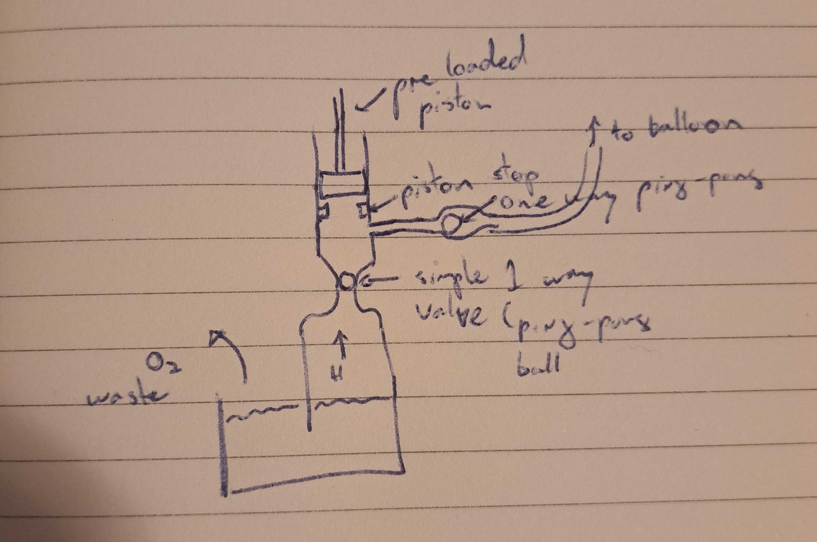
The general idea involves using a few one way vales to let the slow generating air to fill up a cavity (the pre-loaded piston causes little friction and should be able to move with the relatively low pressure from the electrolysis machine. Once it is fill up enough, the piston plunges and closed the electrolysis valve and open the balloon valve. If the total pressure we need is, say 3 bar, then we need to ensure that the volume of air at the maximally retracted piston is 3 times the minimum size of cavity, including tubing to the balloon.
The most important part of this design is to prevent negative pressure at the hydrolysis section, otherwise water would go up and into the cavity. This means the plunger cannot be directly controlled. The second iteration deals with this. It uses a second piston as the driving one. It is not attached to the airtight piston, so it can retract freely. The inner piston can then expand at its own rate.
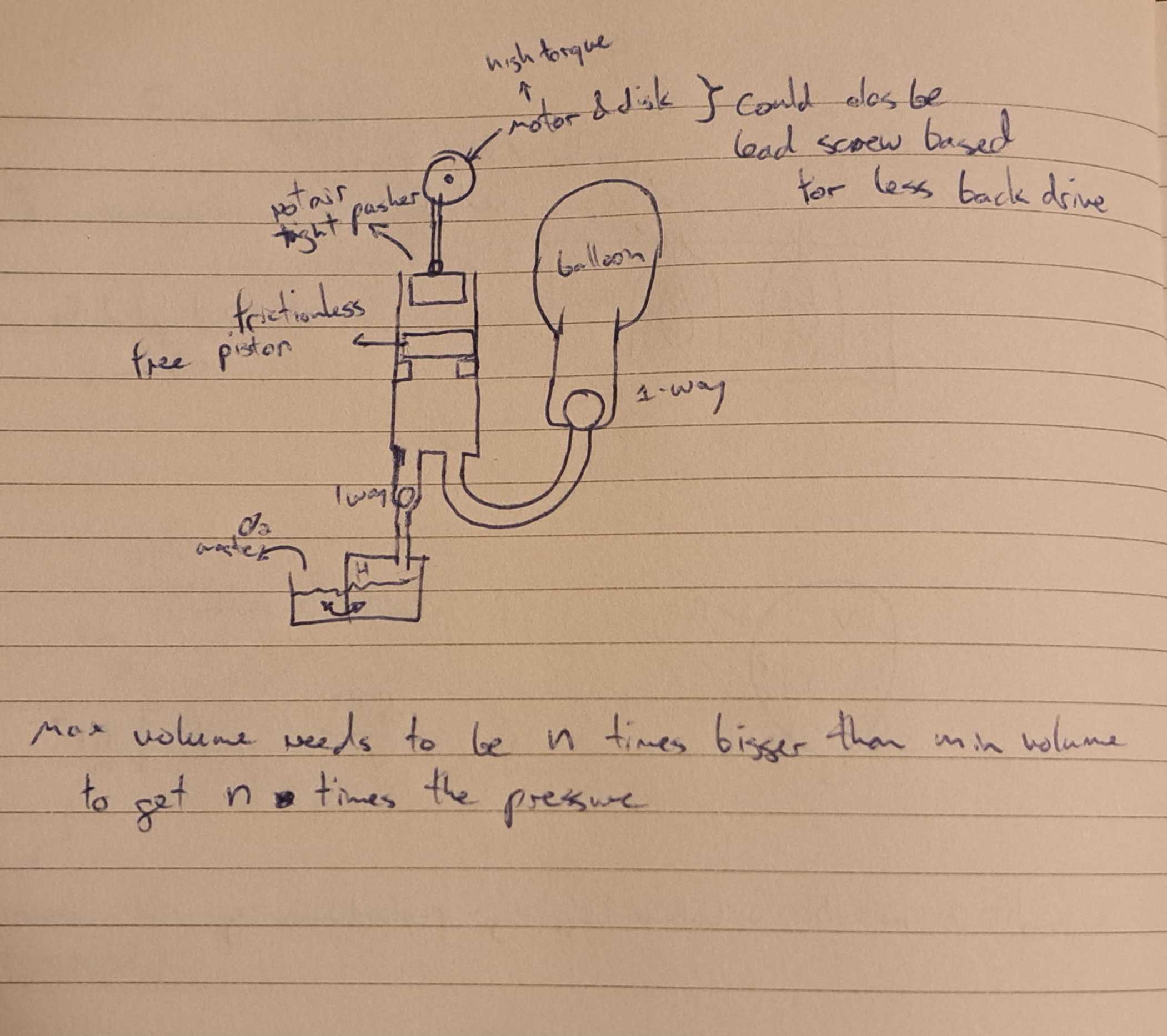
Using a lead screw might be the most sensible way to drive the top piston. Thios would prevent backdriving from the pressure to cause a big holding torque on the motor. The motor would either be a stepper motor or a heavily geared down DC motor.
It is also easy enough to put some limit switches and some markers on the lead screw to be able to know when we are at either end of the motion.
To be honest, I kind of want to make it steam-punky and have a belkow for the inner piston.
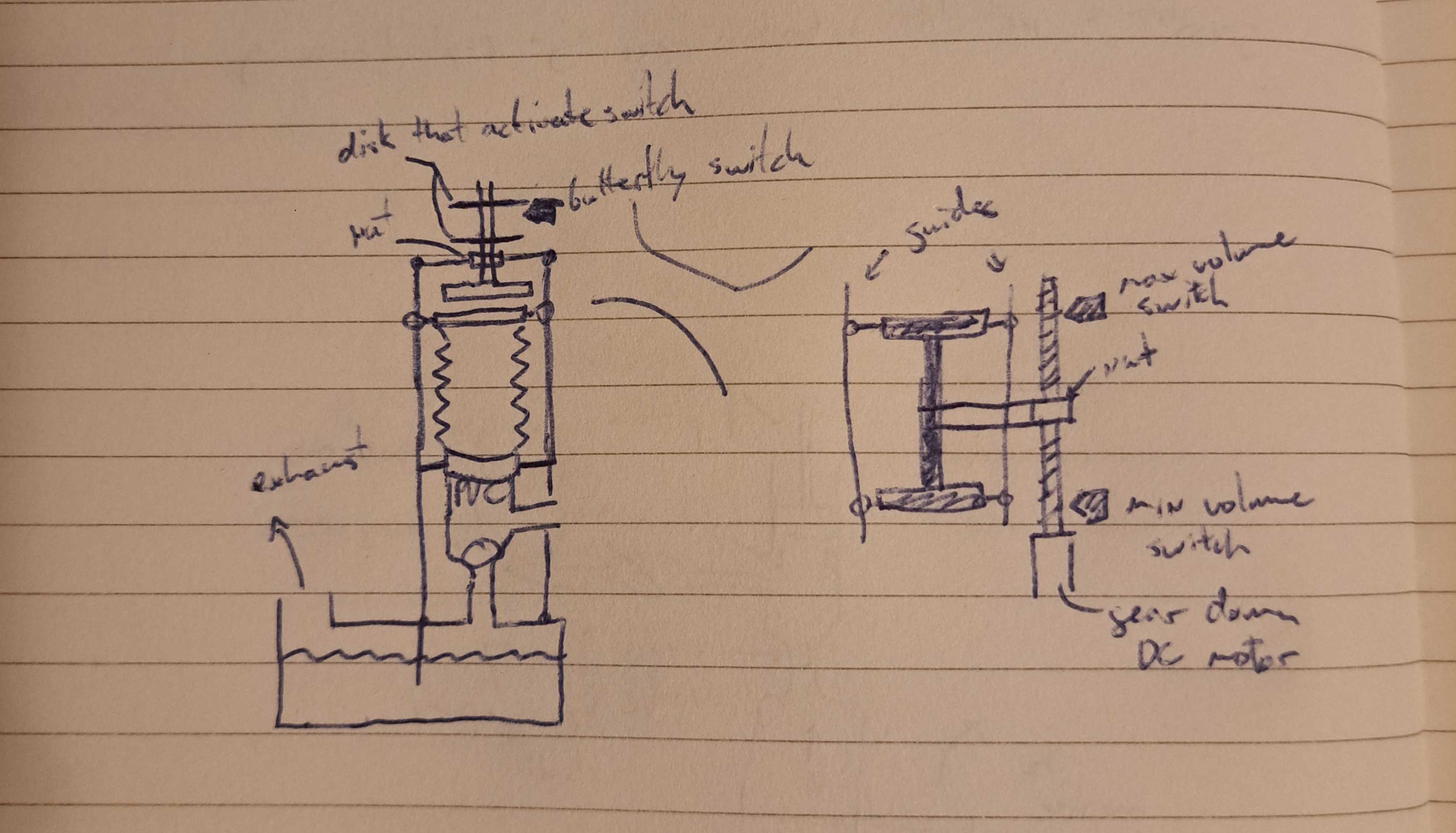
The drive I ended up on uses a lead screw and a nut to both drive the plunger and sense if it is at a limit. The guides ensure that both the plunger and the below are making the correct motion.
Ideally the springiness of the bellow can help counteract some of the friction and the weight of itself (and the top cover).
July 26, 2026: Electrolysis Experiment
11:22pm
After talking to my colleague, my pressure logic was wrong. I am keeping it here because it is a learning thing...
The pressure inside the balloon should be equal in all directions. This would imply that if 300Pa is on the surface of the balloon, it is also on the surface of the water. It should move the water down by 30mm. This is much more manageable. Although (as I'll explain later) I think the water being pushed down slows down the generation speed since less electrode is under water.
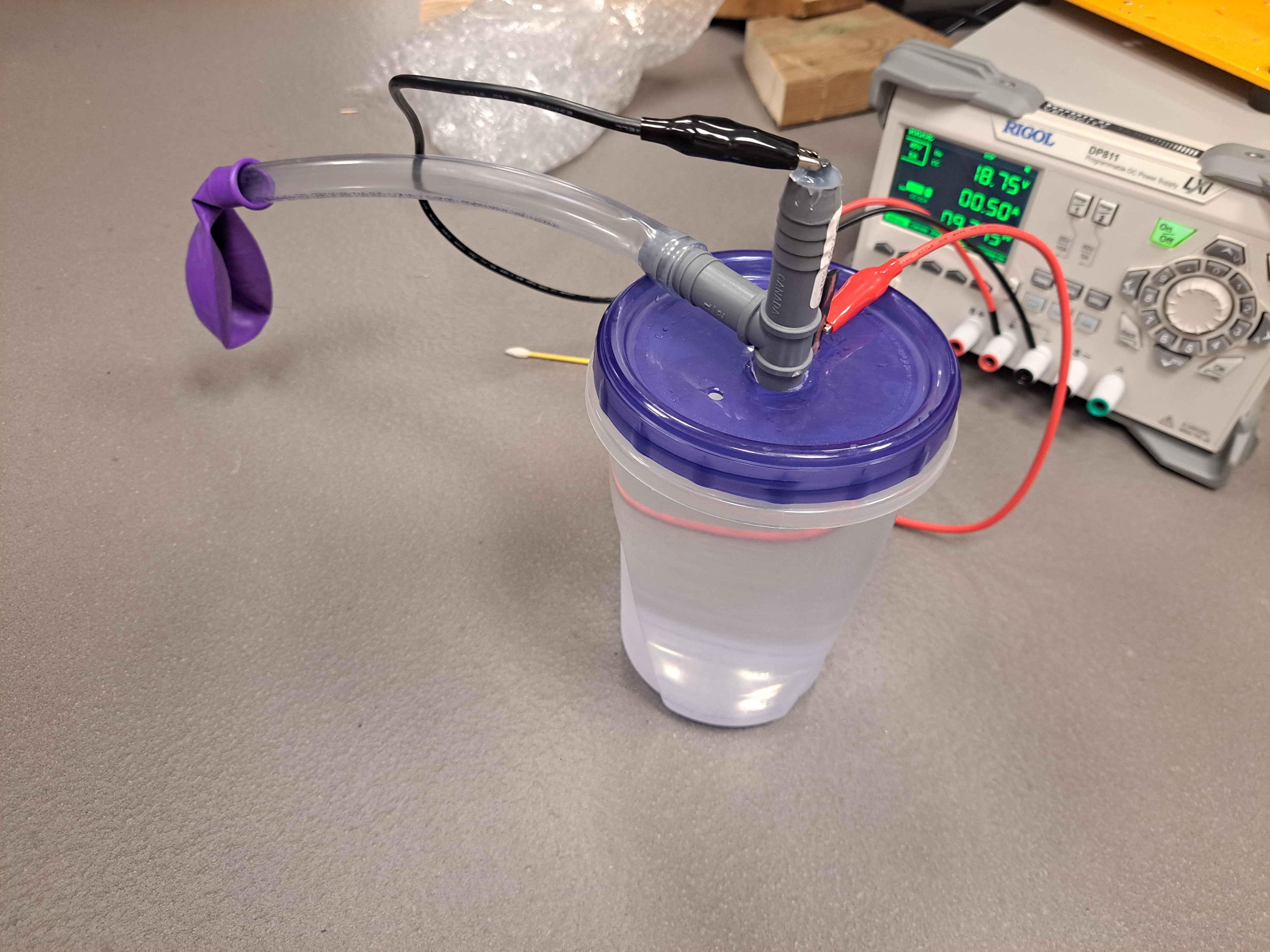
I bought most of the matertial to make a V1. I used the following for this version:
- Ziploc polypropylene container (good for containing strong bases)
- Tee fitting with barbs (1/2 in)
- 1/2 in nylon tubing
- Party balloon (for testing)
- Carpenters pencil for the graphite
I also had laying around a power supply (from work), some pure lye crystals (can be found in a hardware store), and some distilled water (from a supermarket)
Some notes on the experiment:
I did not put much lye to not waste too much but also it was weirdly clumping at the bottom instead of dissolving. I think my stir bar was not deep enough. This is likely why the resistance was as high as it was.
The tee fittin had one side down in the container (hot glues to the lid, doesn't have to be airtight since the only leaks would be oxygen, the waste product). The top had a bit of graphite exposed for the alligator clip, this is the only one that needs to be as airtight as possible. I only had hot glue around so I used that, but will likely replace with sillicone or something else in later iterations. The third outlet was connected to the hose. There was a second graphite in the lid that was also glued to the lid (again, doesn't have to be airtight). There was also another vent hole drilled into the lid.
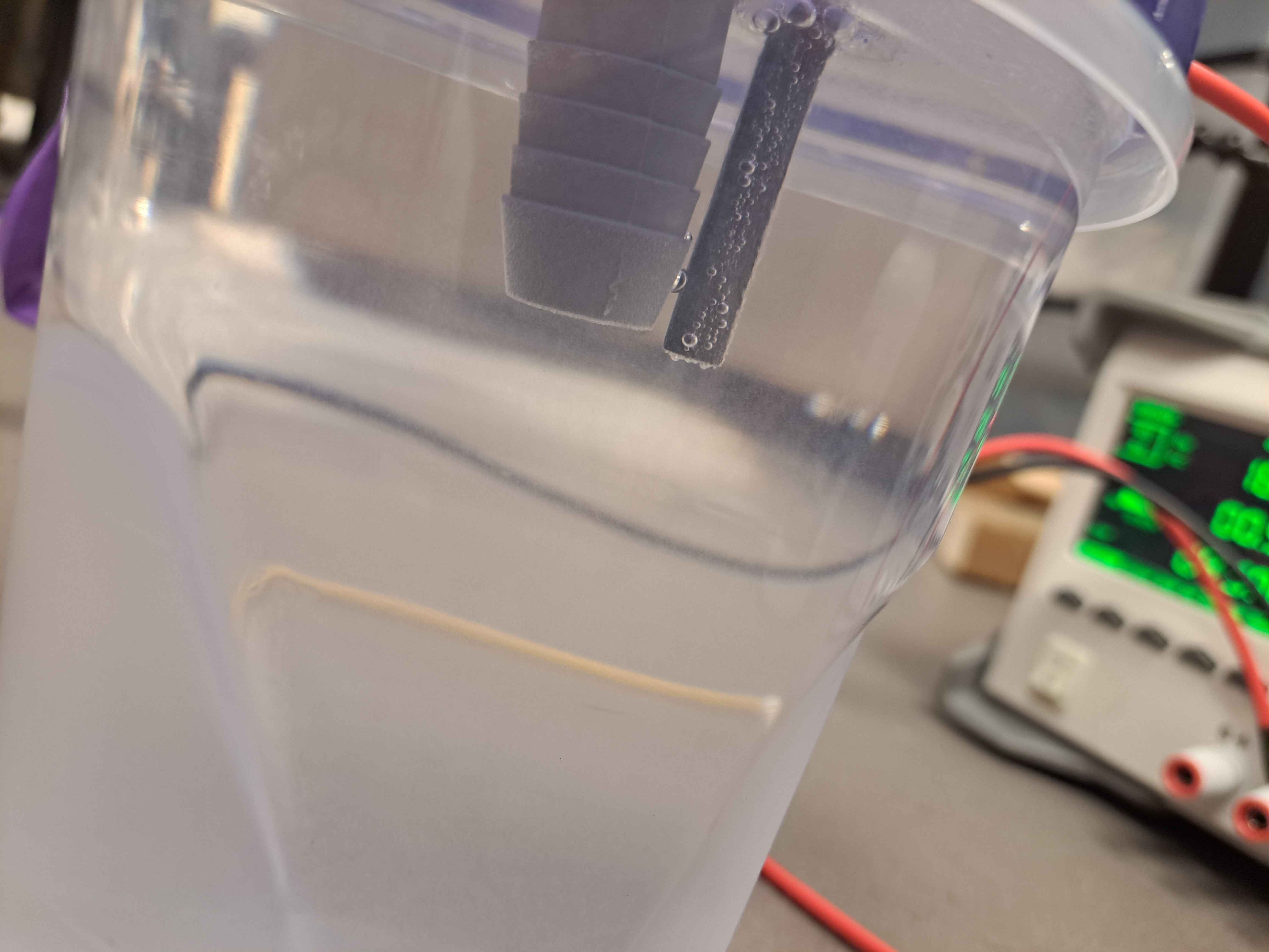
The electrode for the hydrogen has to not show up bellow the fitting, otherwise there is a higher odds of hydrogen leaking outside the fitting from below. This was something I was able to see (not very visible in the picture). I also think my fitting doesn't go deep enough and doesn't allow enough surface area of the graphite.
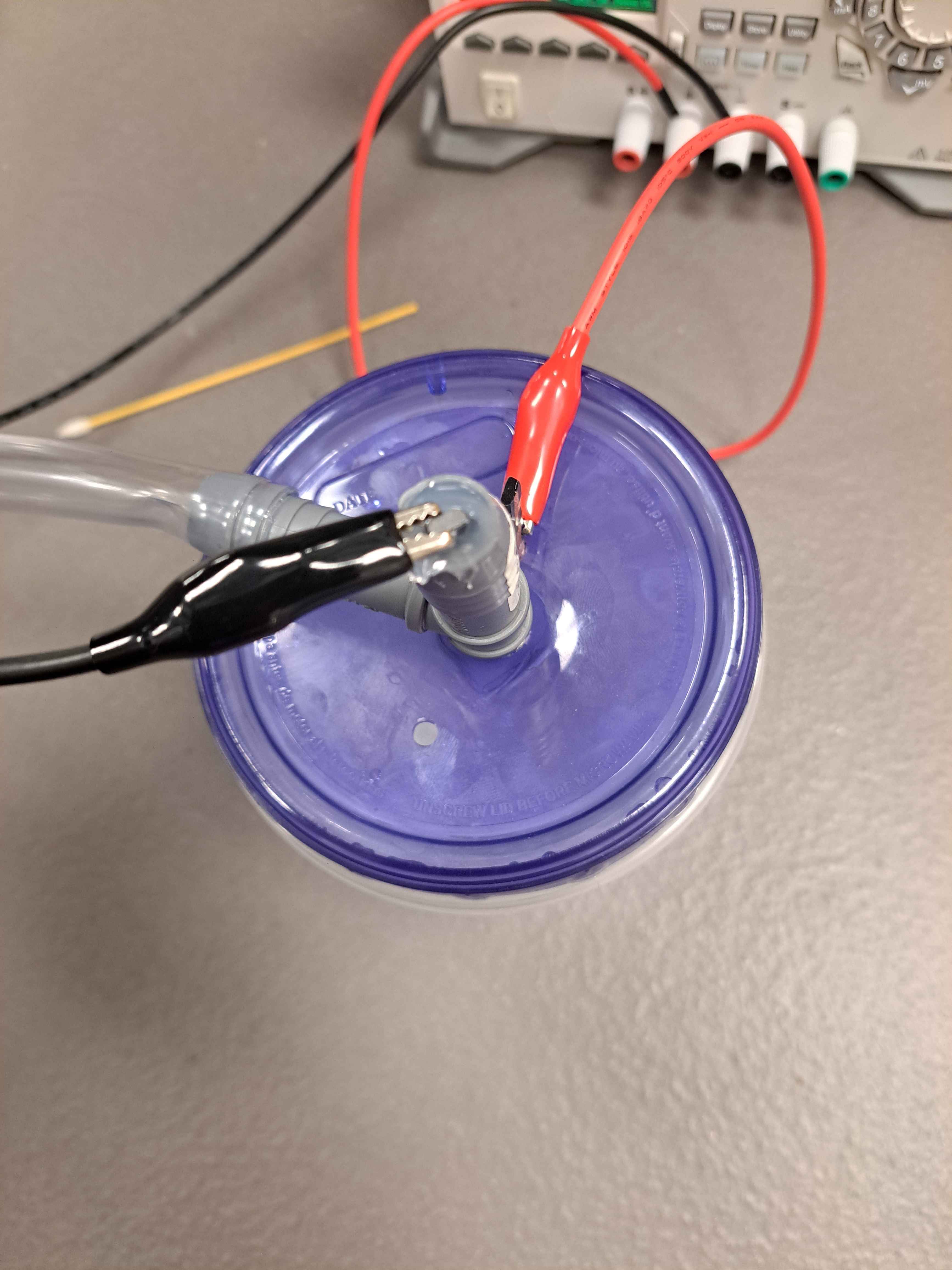
Two interesting facts, that might be related. First, the current would consistently go down over time for a given voltage. If I put 30V 2A, after a few minutes it would drop to 30V 0.5A. I think this is can be because as the balloon fills, it puts pressure on the water, lowering its level and thus the efficiency of the positive electrode. I also think bubbles around the electrode effectively shield it from the water if production is too fast and can't clear the bubble fast enough. This is most evident after a bit at 30V, there were bubble that appeared at the tube outlet. These bubble left on their own, but maybe because the conversion rate dropped.
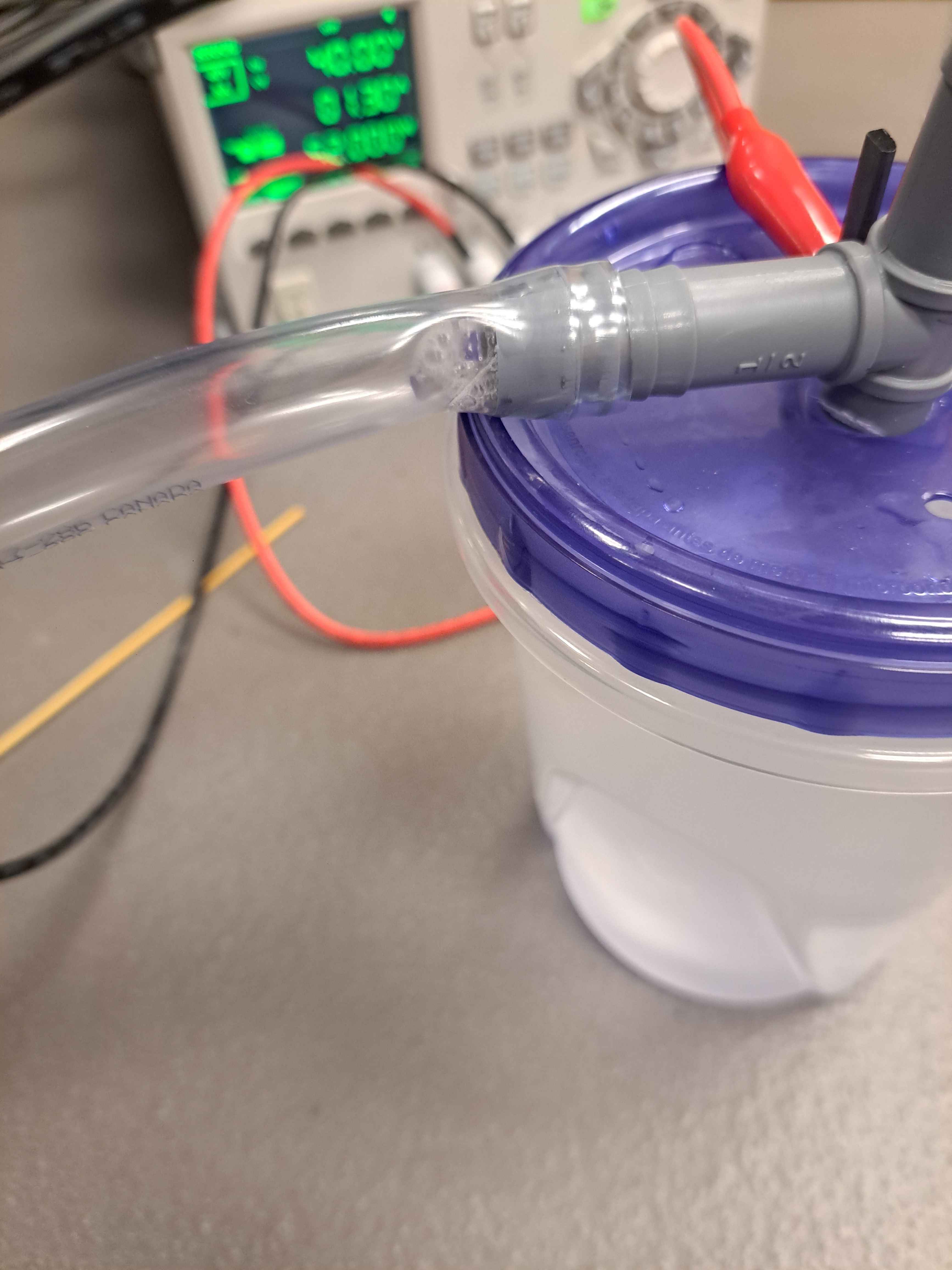
The balloon was able to inflate until taught, I didn't let it go much further since I don't expect the pressure to be this high in real use. I then let the balloon attached for a while to see if it would deflate on its own, a sign that there was a leak, and it did very slowly, so the setup could be improved.
I then tied the balloon off and weighed an empty balloon and the filled balloon to see how much lighter it got. The balloon, when "sphericized", was approximately 52mm diameter, and weighed 0.12g lighter. Supposedly it would be approximately 0.075g lighter if filled with pure hydrogen (heavier than that with anything else). I can chaulk up the difference to the balloons being different themselves. Still a good sign of it being pure hydrogen.
The production rate of gas follow Faraday's Law of Electrolysis:
$$\dot{n}=\frac{\eta I}{zF}$$
Where \(dot{n}\) is rate in moles per second, \(I\) is current in Amps, \(F\) is Faraday's constant (96 485As/mol), \(z\) is number of electrons per ion (2 for H2), and \(\eta\) is the efficiency (usually 0.9 to 0.99 if well done?). For the volume, we use the ideal gas law to get the approximate molar volume of \(\dot{V} \approx 22.4 L/mol\) at room temperature and ambient pressure.
This leads to a total volume production rate \(r\) of approximately, assuming a (conservative?) efficiency of 80%:
$$r(I)=\dot{V}\dot{n}=\frac{\eta I \dot{V}}{zF}=\frac{0.8 \cdot 22.4 \frac{L}{mol}}{2 \cdot 96.5 \frac{kAs}{mol}} I \approx 0.1 [\frac{ml}{As}] \cdot I [A]$$
This means for every amp that is pumped, I would get 0.1ml/s. This is very slow. The total volume of a 1m sphere (my generic metric) is 525L, which would imply:
$$t_{fill}=\frac{525 L}{0.1 \frac{ml}{As} \cdot I}=\frac{5.25}{I} Ms = \frac{1460}{I} hrs$$
Thats a lot of time!
July 27, 2026: Aluminium Reaction Design
9:00pm
After further thinking, the pace of the electrolysis method will be too slow for in-field deployement. An alternative design, although WARNING more dangerous, is to mix lye and aluminium in water. The reaction that occurs is:
$$2Al_{(s)} + 2NaOH_{(aq)} + 6H_{2}O_{(l)} \longrightarrow 2Na[Al(OH)_{4}]_{(aq)} + 3H_{2(g)}$$
This reaction is very exothermic however so it needs to be designed with a lot of safety.
The general idea is to have a mechanism that can safely drop a small amount of aluminium at a time, let the reaction occur and let the water cool back down before putting the next one. The main parts are the feeder and the cooling column. Since I don't have a cooling column and don't think it'll work perfectly, I think I will base my design in multiple water "arresters", where each one successively cools down the gas (letting the water vapour and any other gasses mix with the water. Only the hydrogen should keep going. The final one can connect directly to the balloon since the reaction should be capable of creating enough pressure.
Since the pressure from the balloon should only push the water down by 30mm, as long as the last arrestor is submerged with more than 30mm, it should be ok.
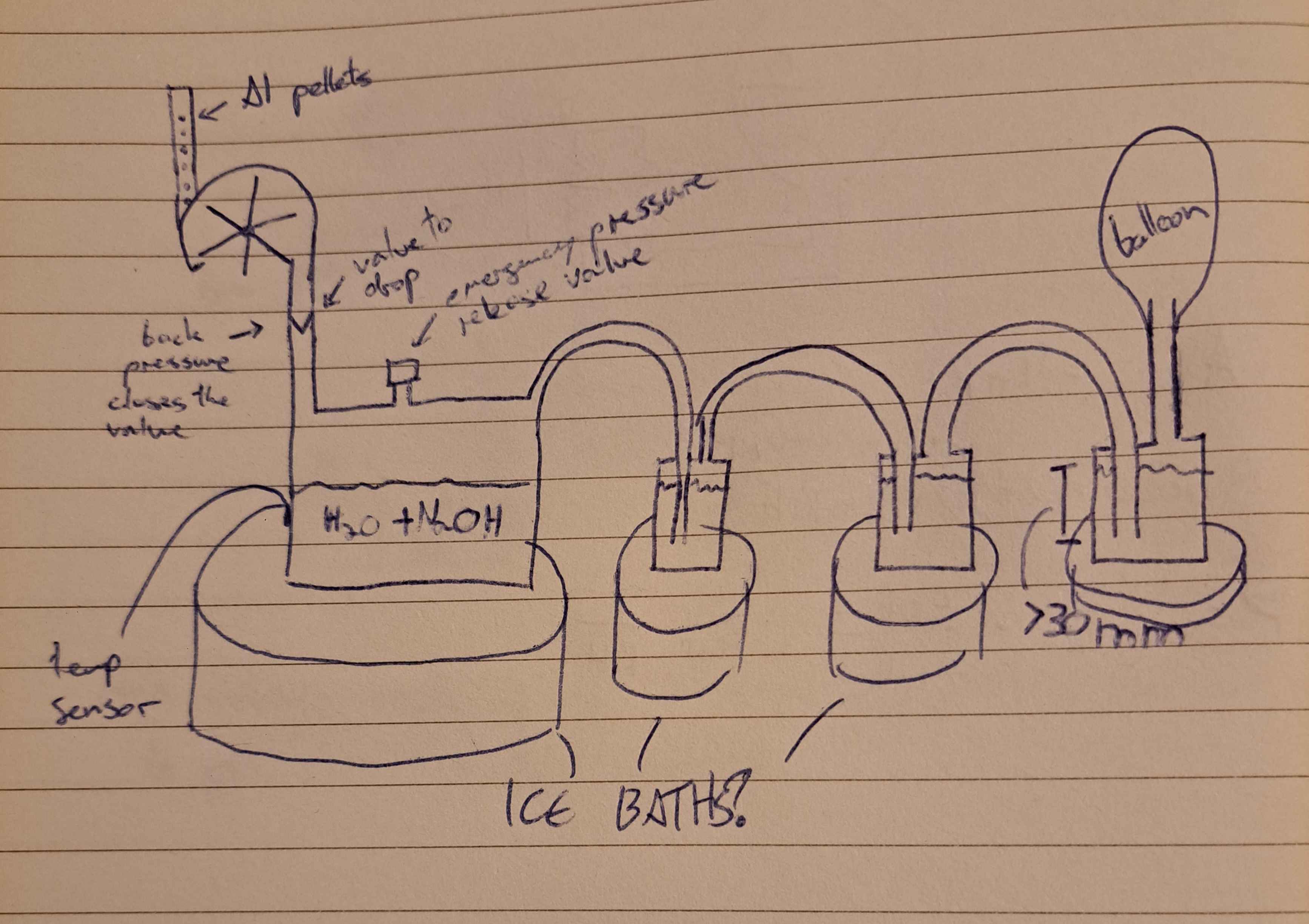
Ideally the material used is something like Stainless Steel, but I feel it is important to be able to see inside the reaction as it occurs, so I'm not sure. The stell would make it easier to cool down the system in an ice bath or any active cooling solution. The later stages are likely not as critical.
One important thing to mention is that any metal should be grounded and possibly a mist will be sprayed as the balloon inflates since the balloon could have some static. It should also likely be placed on an ESD mat.
Since the vapour generated is caustic, every part of the reaction process should be made of material that can handle it.
The size of the pellets are also very important. Since they dictate the increments of gas that can be added at once (unless a second escape valve is added between the penultimate and ultimate arrester, which might be a good idea in general, also helps with emptying out the system of non-hydrogen before filling the balloon).
My current idea is to have the last (2?) containers be out of plastic (polypropylene) since they should neither deal with very cold nor very hot temperatures. Since plastic gets brittle and may start leaking if submerged at cold temperatures, it should also not be in an ice bath. The tubing by then can also be plastic if needed since it is cheaper.
The depth of the first arrester's tube indicates the resting pressure of the chamber, since that will determine when there is not enough pressure to go underneath the tube, at approximately 10mm per 100Pa.
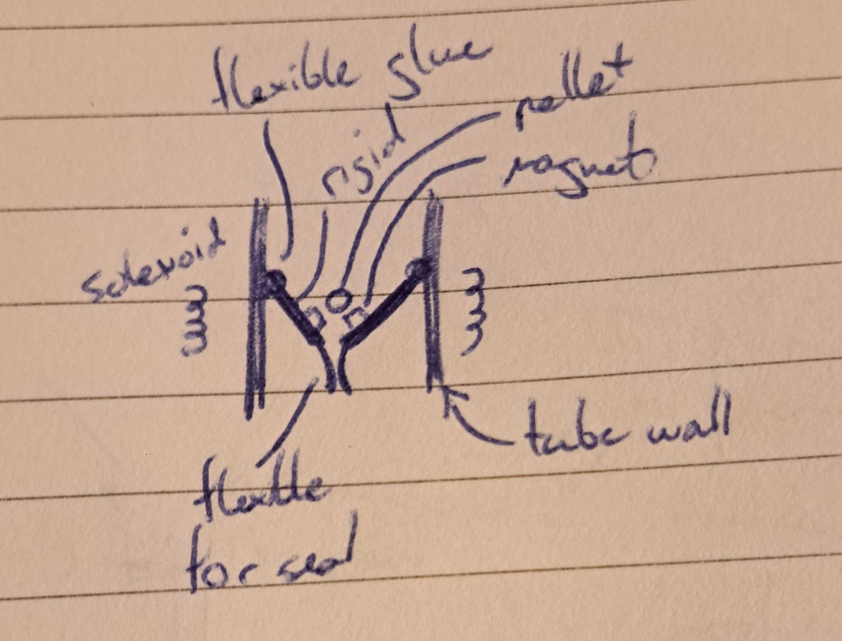
The one way valve for the hopper section needs to be airtight when closed but let a small pellet in when opened. The design in mind is akin to what they use in water locks, which uses the pressure of the chamber itself to ensure the valve closes. This also makes it harder to accidentally open the valve when the reaction is pressurized a lot. To operate the valve, maybe we can attach small magnets to silicone flaps. The flaps will prevent the backflow of pressure and the magnets, along with some solenoid on the outside, will allow it to open when we want the Al to fall through. Ideally some sort of silicone flap with a soft section at the end but a rigid in the center (like a spatula!). The hard part is the have the hinge be airtight as well. I am considering using a silicone glue that should stay relatively flexible for it. That tube can be square to make contruction easier. Since aluminium is not magnetic, it shouldn't get stuck on the magnets.
Neodynium might not like reacting with the water vapours. Even though it would be on the upper side and should be exposed to it, might be worth looking for alternates (cermic ferrite)?
Since the pellets should be small, the valve shouldn't have to open up very much.
Speaking of the pellet size, we can find the approximate volume of gas produced per volume of Al. Every 2 mols of Al gives 3 mols of H2. Since Al has a density of 2.70g/cm3 and a molar mass of 26.98g/mol. Hydrogen gas on the other side is (under ideal gas law) 22.4L/mol. Thus:
$$\dot{V_{H_{2}}} = 22.4\frac{L}{mol_{H_{2}}} \cdot \frac{3}{2} \frac{mol_{H_{2}}}{mol_{Al}} \cdot \frac{1}{27}\frac{mol_{Al}}{g} = 1.24 \frac{L}{g_{Al}} \rightarrow 3.36\frac{L}{cm_{Al}^3}$$
Similarly for the lye (molar mass of 40g/mol):
$$\dot{V_{H_{2}}} = 22.4\frac{L}{mol_{H_{2}}} \cdot \frac{3}{2} \frac{mol_{H_{2}}}{mol_{NaOH}} \cdot \frac{1}{40}\frac{mol_{NaOH}}{g} = 0.84 \frac{L}{g_{NaOH}}$$
For the same 1m diameter sphere (525L) that means approximately 625g of NaOH and 420g of Al. This is much more reasonable.
Howver this does mean that the pellets of Al needed are relatively small. If we want 1% control for the sphere, that means approximately 4.2g per pellet. However 5.25L at a time might be alot, especially if it needs to be stopped in an emergency.
500g of Al as a 1/8 inch rod has a length of:
$$L = \frac{V}{\pi r^2} = \frac{m}{\pi \rho r^2} = \frac{500g}{\pi 2.70\frac{g}{cm^3} (0.3175cm)^2} = 5.85m$$
For a 1/4 inch rod:
$$L = \frac{500g}{\pi 2.70\frac{g}{cm^3} (0.635cm)^2} = 1.46m$$
Each 5g pellet would then be 1.46cm tall, very reasonable.
To make the feeder, I will use pvc hose, since I already have some as the magazine, which will then get pushed via a servo (mostly because I already have one and they are cheap enough). This then falls into a 2 inch (or 1 1/2 inch) PVC pipe that will contain the valve. Then at the bottom will be the container. The valve will exhaust air into the enironment, but that is likely safer than letting any amount of the vapours interact with the rod in the magazine.
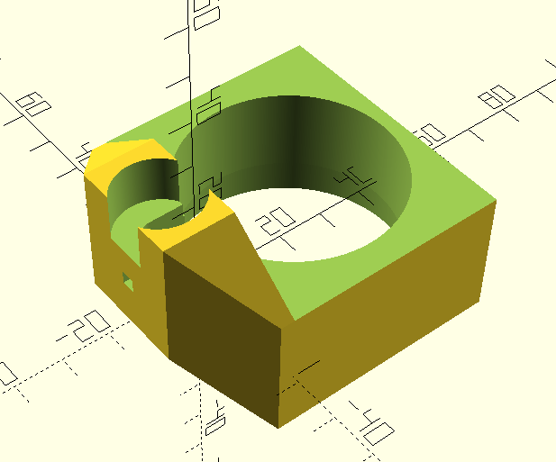
All that section before the valve can be 3D printed. It will make it easier to iterate and replace. I need to finish the mount for the servo motor behind the push rod slot. I also need to design the flaps for the valv. It will likely be a 1 flap design instead of 2, since it'll make there be less magnets inside the setup (that can interact with each other).