<?xml version="1.0" encoding="utf-8"?>
<feed xmlns="http://www.w3.org/2005/Atom" xmlns:media="http://search.yahoo.com/mrss/">
    <title>JAMR&#x27;s Lab Notes</title>
    <link href="https://jmarcano.ca/feed.xml" rel="self" />
    <link href="https://jmarcano.ca" />
    <updated>2026-07-28T00:46:03-04:00</updated>
    <author>
        <name>JAMR</name>
    </author>
    <id>https://jmarcano.ca</id>

    <entry>
        <title>Weather Balloon Filling Station</title>
        <author>
            <name>JAMR</name>
        </author>
        <link href="https://jmarcano.ca/weather-balloon-filling-station.html"/>
        <id>https://jmarcano.ca/weather-balloon-filling-station.html</id>
            <category term="weather balloon"/>
            <category term="random"/>
            <category term="in progress"/>

        <updated>2026-07-25T21:09:53-04:00</updated>
            <summary type="html">
                <![CDATA[
                    This is the subproject of the Weather Balloon Project. The requirements are copied here: This part is likely the most dangerous, but also the simplest.
                ]]>
            </summary>
        <content type="html">
            <![CDATA[
                <p>This is the subproject of the <a href="https://jmarcano.ca/weather-balloon-exploration.html">Weather Balloon Project</a>. The requirements are copied here:</p>
<h2 id="mcetoc_1juj5npjb680">Filling and Release Subsystem</h2>
<p>This part is likely the most dangerous, but also the simplest. The idea is that using electrolysis, it should be possible to get a very cheap supply of very pure hydrogen. It will consist of 3 parts.</p>
<h3 id="mcetoc_1juj5npjb681">A. Electrolysis</h3>
<p>This section is simply distilled water with some current carriers (salts) along with 2 electrodes. One of the electrodes will be the section that generates the hydrogen. This means there is a separation between the two and it will funnel into a hydrogen supply outlet. The ON/OFF and power control from this will be remotely controlled (using a wired connection). This will allow for monitoring and safety by not needing to have someone nearby.</p>
<h3 id="mcetoc_1juj5npjb682">B. Outlet</h3>
<p>This section is in charge of making sure the hydrogen goes inside the balloon only in one way. It is also responsible for sealing the balloon once it is full, so some automated way should be figured out (a one way valve perhaps).</p>
<p>The hardest part of this is that it needs to make sure that the hydrogen has enough pressure to go into the balloon. Maybe a water based system, where the hydrogen goes through water is the simplest way. However it prevents the use of a one way valve from being part of the balloon system, so an alternate way of sealing the balloon would be necessary.</p>
<h3 id="mcetoc_1juj5npjb683">C. Release mechanism</h3>
<p>This section is in charge of holding down the balloon until it is filled enough and having a way to sense when it acheives neutral bouyancy (+ free lift requirements). Once that is reached, it is able to separate the outlet from the balloon (in tandem with the outlet sealing the balloon), and releasing its grip from it so it can go in the air. It needs to be tall enough to have the electronics not drag on the ground as it is released.</p>
<div class="post__toc">
<h3>Table of Contents</h3>
<ul>
<li><a href="#mcetoc_1juj5npjb680">Filling and Release Subsystem</a>
<ul>
<li><a href="#mcetoc_1juj5npjb681">A. Electrolysis</a></li>
<li><a href="#mcetoc_1juj5npjb682">B. Outlet</a></li>
<li><a href="#mcetoc_1juj5npjb683">C. Release mechanism</a></li>
</ul>
</li>
<li><a href="#mcetoc_1juj5npjb684">July 25, 2026: Electrolysis Design</a>
<ul>
<li><a href="#mcetoc_1juj5npjb685">8:10pm</a></li>
<li><a href="#mcetoc_1juj5npjb686">10:30pm</a></li>
</ul>
</li>
<li><a href="#mcetoc_1juj5npjb687">July 26, 2026: Electrolysis Experiment</a>
<ul>
<li><a href="#mcetoc_1juj5npjb688">11:22pm</a></li>
</ul>
</li>
<li><a href="#mcetoc_1juj5npjb689">July 27, 2026: Aluminium Reaction Design</a>
<ul>
<li><a href="#mcetoc_1juj5npjb68a">9:00pm</a></li>
</ul>
</li>
</ul>
</div>
<h2 id="mcetoc_1juj5npjb684">July 25, 2026: Electrolysis Design</h2>
<h3 id="mcetoc_1juj5npjb685">8:10pm</h3>
<p>I remebered having watched videos on electrolysis before and decided to find it again. This <a href="https://youtu.be/d85OX6yEwE0?si=AnvYk3Gv-3EqGKaT" target="_blank" rel="noopener noreferrer">first</a> one is probably closer to what we want. This <a href="https://youtu.be/eq7fR9ISuCw?t=2066&amp;si=PGvh1lFum2CGU45f" target="_blank" rel="noopener noreferrer">second</a> one is more about ion exchange membranes, which would only be needed if we need to increase the pressure it can make or the efficiency.</p>
<p>In an ideal balloon with no stretch, the pressure inside the balloon and outside the balloon would be equal. This means the there would be no net presure. However, since the balloon is out of latex, it will generate a restoring force. This pressure is usually in the order of 100-300Pa [<a href="https://zmatt.net/weather-balloon-physics/" target="_blank" rel="noopener noreferrer">1</a>]. For a radius r, this means that the total force is:</p>
<p>[Note: This following section is wrong, leaving it here for posteriority]</p>
<p>$$F=P A = P \cdot 4 \pi r^2$$</p>
<p>If the water opening diameter is d, then that force will excert a presure on the water surface of:</p>
<p>$$P_{water}= \frac{F}{\frac{\pi d^2}{4}} = \frac{16P r^2}{d^2}$$</p>
<p>Using some general numbers to get an order of mangintude estimate (P=200Pa, r=1m, d=0.1m):</p>
<p>$$P_{water}=320kPa$$</p>
<p>This will displace the water by:</p>
<p>$$ \Delta h_{water} = \frac{P_{water} - P_{air}}{g \rho_{water}}  = \frac{320kPa - 100kPa}{1000 \frac{kg}{m^3} \cdot 9.8 \frac{m}{s^2}} = 22.5m$$</p>
<p>Ouch, that is a lot, the column needed to handle that would be unusable for electrolysis.</p>
<p>Some mechanism for compression would need to be made. If, however, we use the second video's idea, it becomes much more manageable, albeit harder to make.</p>
<h3 id="mcetoc_1juj5npjb686">10:30pm</h3>
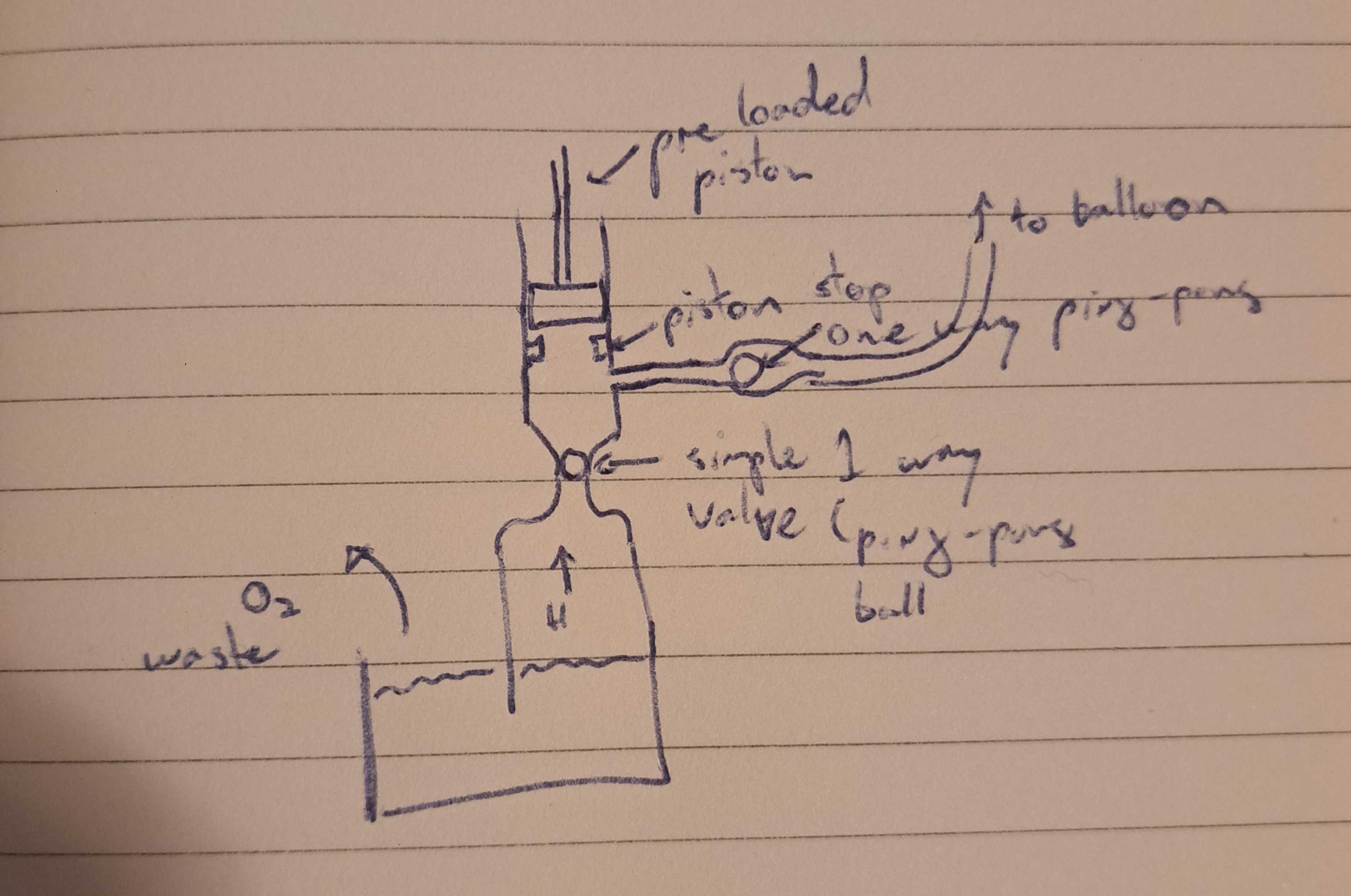
<p>After discussing with my colleague Leo, I feel confident some form of compressor would not be difficult to make. A piston/syringe/bellow style compressor would have the lowest odds of a spark if everything is made of plastic.</p>
<figure class="post__image"><img loading="lazy" src="https://jmarcano.ca/media/posts/15/20260725_220404.jpg" alt="" width="3099" height="2056" sizes="(min-width: 920px) 703px, (min-width: 700px) calc(82vw - 35px), calc(100vw - 81px)" srcset="https://jmarcano.ca/media/posts/15/responsive/20260725_220404-xs.jpg 300w ,https://jmarcano.ca/media/posts/15/responsive/20260725_220404-sm.jpg 480w ,https://jmarcano.ca/media/posts/15/responsive/20260725_220404-md.jpg 768w ,https://jmarcano.ca/media/posts/15/responsive/20260725_220404-lg.jpg 1024w">
<figcaption>First iteration, figuring out the general mechanism</figcaption>
</figure>
<p>The general idea involves using a few one way vales to let the slow generating air to fill up a cavity (the pre-loaded piston causes little friction and should be able to move with the relatively low pressure from the electrolysis machine. Once it is fill up enough, the piston plunges and closed the electrolysis valve and open the balloon valve. If the total pressure we need is, say 3 bar, then we need to ensure that the volume of air at the maximally retracted piston is 3 times the minimum size of cavity, including tubing to the balloon.</p>
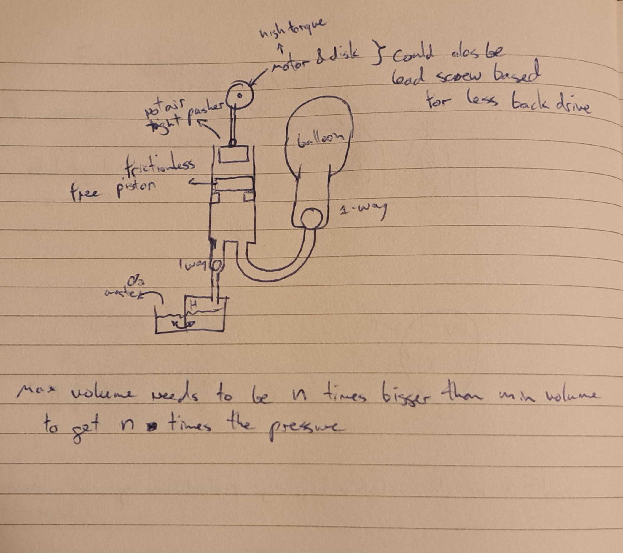
<p>The most important part of this design is to prevent negative pressure at the hydrolysis section, otherwise water would go up and into the cavity. This means the plunger cannot be directly controlled. The second iteration deals with this. It uses a second piston as the driving one. It is not attached to the airtight piston, so it can retract freely. The inner piston can then expand at its own rate.</p>
<figure class="post__image"><img loading="lazy" src="https://jmarcano.ca/media/posts/15/20260725_222750.jpg" alt="" width="2101" height="1866" sizes="(min-width: 920px) 703px, (min-width: 700px) calc(82vw - 35px), calc(100vw - 81px)" srcset="https://jmarcano.ca/media/posts/15/responsive/20260725_222750-xs.jpg 300w ,https://jmarcano.ca/media/posts/15/responsive/20260725_222750-sm.jpg 480w ,https://jmarcano.ca/media/posts/15/responsive/20260725_222750-md.jpg 768w ,https://jmarcano.ca/media/posts/15/responsive/20260725_222750-lg.jpg 1024w">
<figcaption>Second iteration</figcaption>
</figure>
<p>Using a lead screw might be the most sensible way to drive the top piston. Thios would prevent backdriving from the pressure to cause a big holding torque on the motor. The motor would either be a stepper motor or a heavily geared down DC motor.</p>
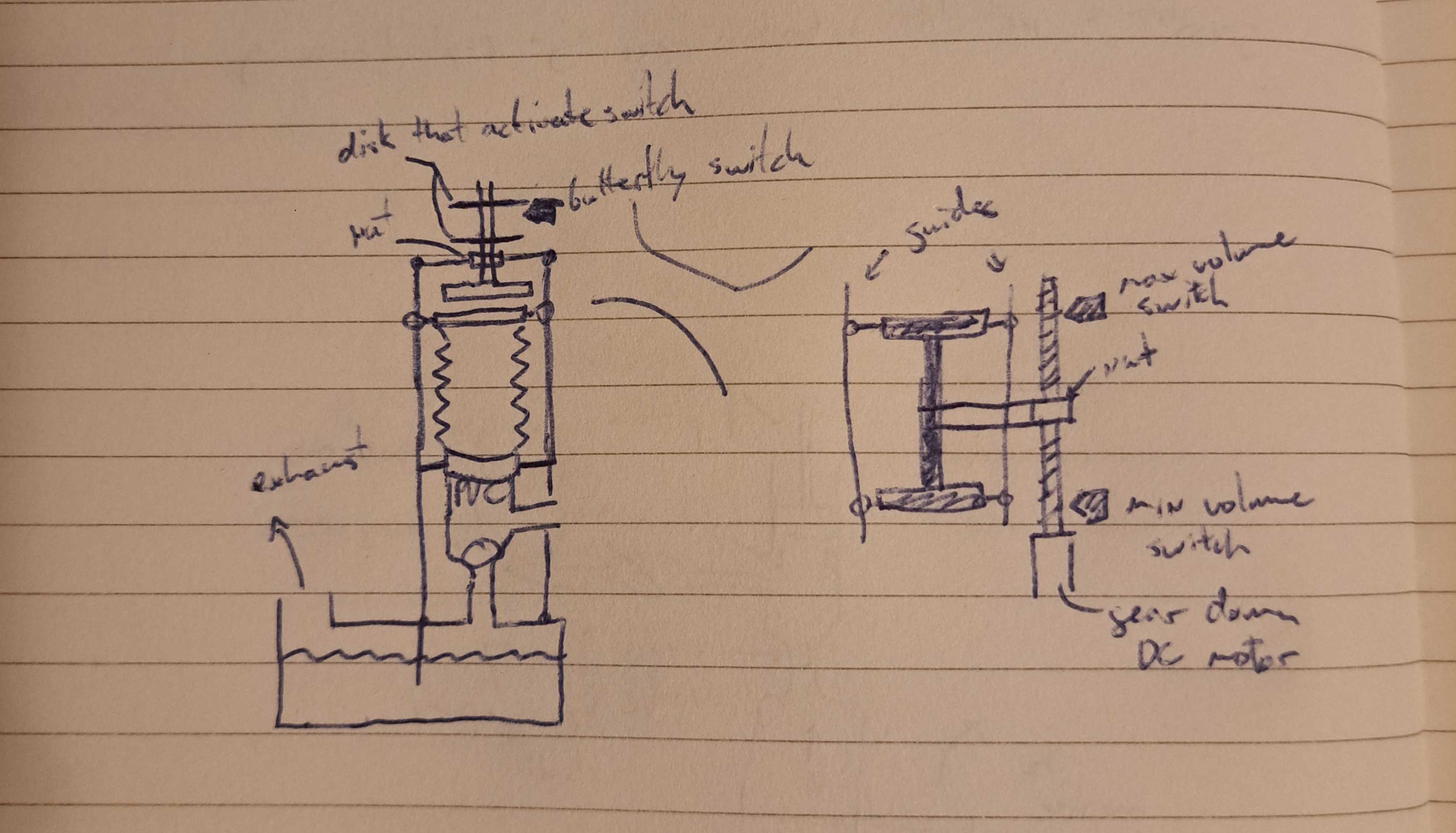
<p>It is also easy enough to put some limit switches and some markers on the lead screw to be able to know when we are at either end of the motion.</p>
<p>To be honest, I kind of want to make it steam-punky and have a belkow for the inner piston.</p>
<figure class="post__image"><img loading="lazy" src="https://jmarcano.ca/media/posts/15/20260725_231539.jpg" alt="" width="3468" height="1985" sizes="(min-width: 920px) 703px, (min-width: 700px) calc(82vw - 35px), calc(100vw - 81px)" srcset="https://jmarcano.ca/media/posts/15/responsive/20260725_231539-xs.jpg 300w ,https://jmarcano.ca/media/posts/15/responsive/20260725_231539-sm.jpg 480w ,https://jmarcano.ca/media/posts/15/responsive/20260725_231539-md.jpg 768w ,https://jmarcano.ca/media/posts/15/responsive/20260725_231539-lg.jpg 1024w">
<figcaption>Third attempt, trying to describe the driving mechanism in more detail</figcaption>
</figure>
<p>The drive I ended up on uses a lead screw and a nut to both drive the plunger and sense if it is at a limit. The guides ensure that both the plunger and the below are making the correct motion.</p>
<p>Ideally the springiness of the bellow can help counteract some of the friction and the weight of itself (and the top cover).</p>
<h2 id="mcetoc_1juj5npjb687">July 26, 2026: Electrolysis Experiment</h2>
<h3 id="mcetoc_1juj5npjb688">11:22pm</h3>
<p>After talking to my colleague, my pressure logic was wrong. I am keeping it here because it is a learning thing...</p>
<p>The pressure inside the balloon should be equal in all directions. This would imply that if 300Pa is on the surface of the balloon, it is also on the surface of the water. It should move the water down by 30mm. This is much more manageable. Although (as I'll explain later) I think the water being pushed down slows down the generation speed since less electrode is under water.</p>
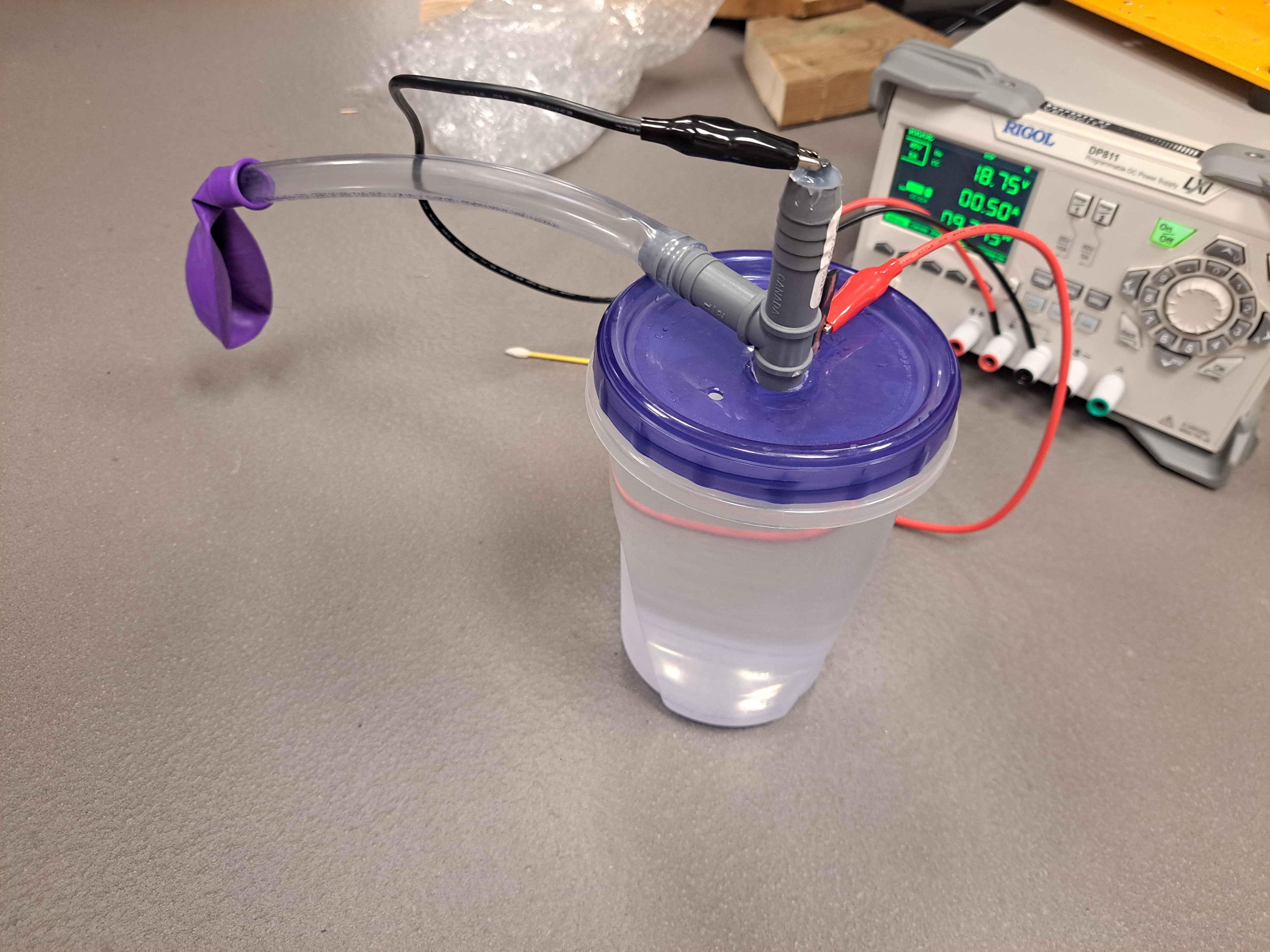
<p>I bought most of the matertial to make a V1. I used the following for this version:</p>
<ul>
<li>Ziploc polypropylene container (good for containing strong bases)</li>
<li>Tee fitting with barbs (1/2 in)</li>
<li>1/2 in nylon tubing</li>
<li>Party balloon (for testing)</li>
<li>Carpenters pencil for the graphite</li>
</ul>
<p>I also had laying around a power supply (from work), some pure lye crystals (can be found in a hardware store), and some distilled water (from a supermarket)</p>
<figure class="post__image"><img loading="lazy" src="https://jmarcano.ca/media/posts/15/20260726_200852.jpg" alt="" width="4624" height="3468" sizes="(min-width: 920px) 703px, (min-width: 700px) calc(82vw - 35px), calc(100vw - 81px)" srcset="https://jmarcano.ca/media/posts/15/responsive/20260726_200852-xs.jpg 300w ,https://jmarcano.ca/media/posts/15/responsive/20260726_200852-sm.jpg 480w ,https://jmarcano.ca/media/posts/15/responsive/20260726_200852-md.jpg 768w ,https://jmarcano.ca/media/posts/15/responsive/20260726_200852-lg.jpg 1024w">
<figcaption>Initial Setup</figcaption>
</figure>
<p>Some notes on the experiment:</p>
<p>I did not put much lye to not waste too much but also it was weirdly clumping at the bottom instead of dissolving. I think my stir bar was not deep enough. This is likely why the resistance was as high as it was.</p>
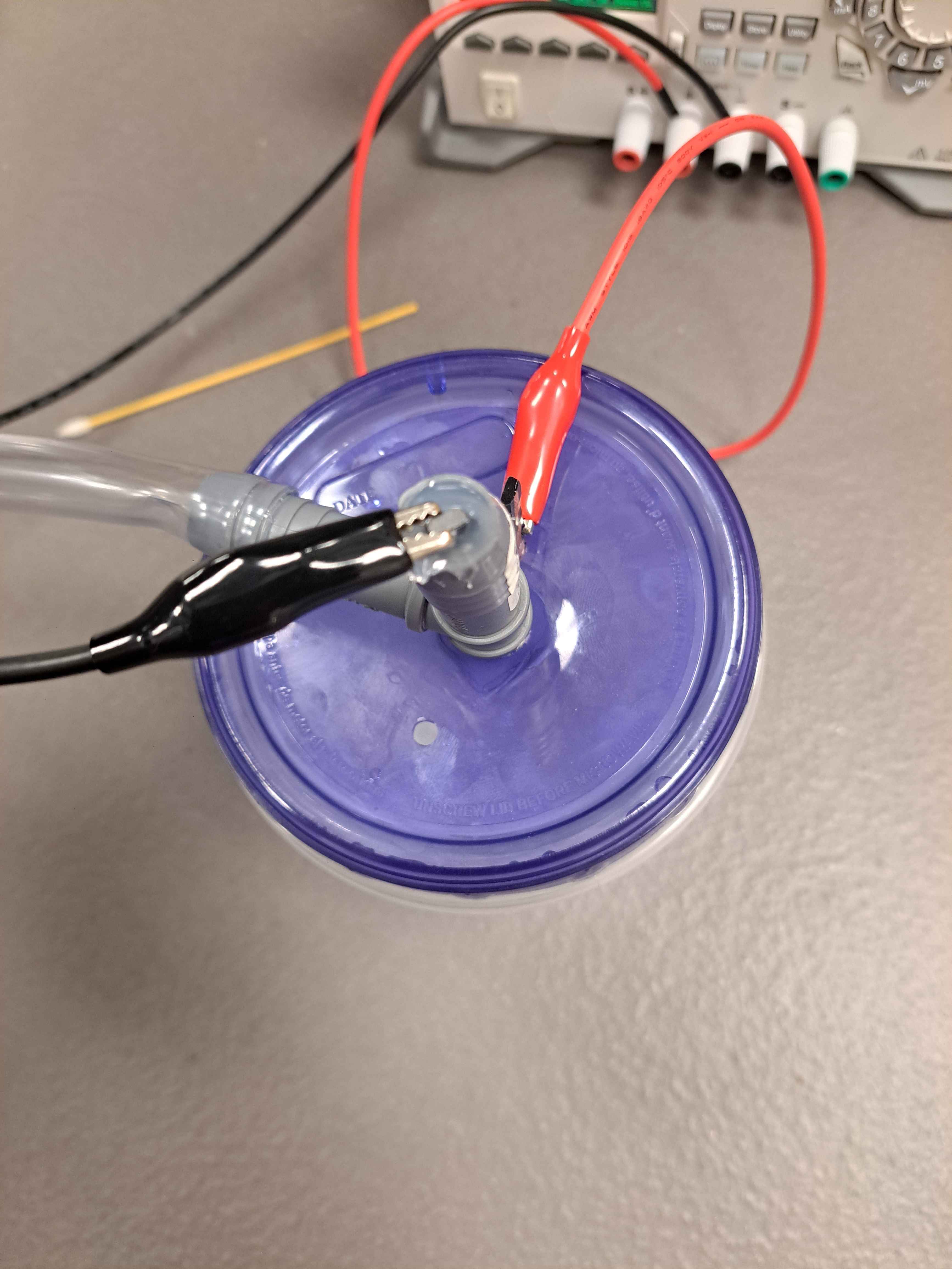
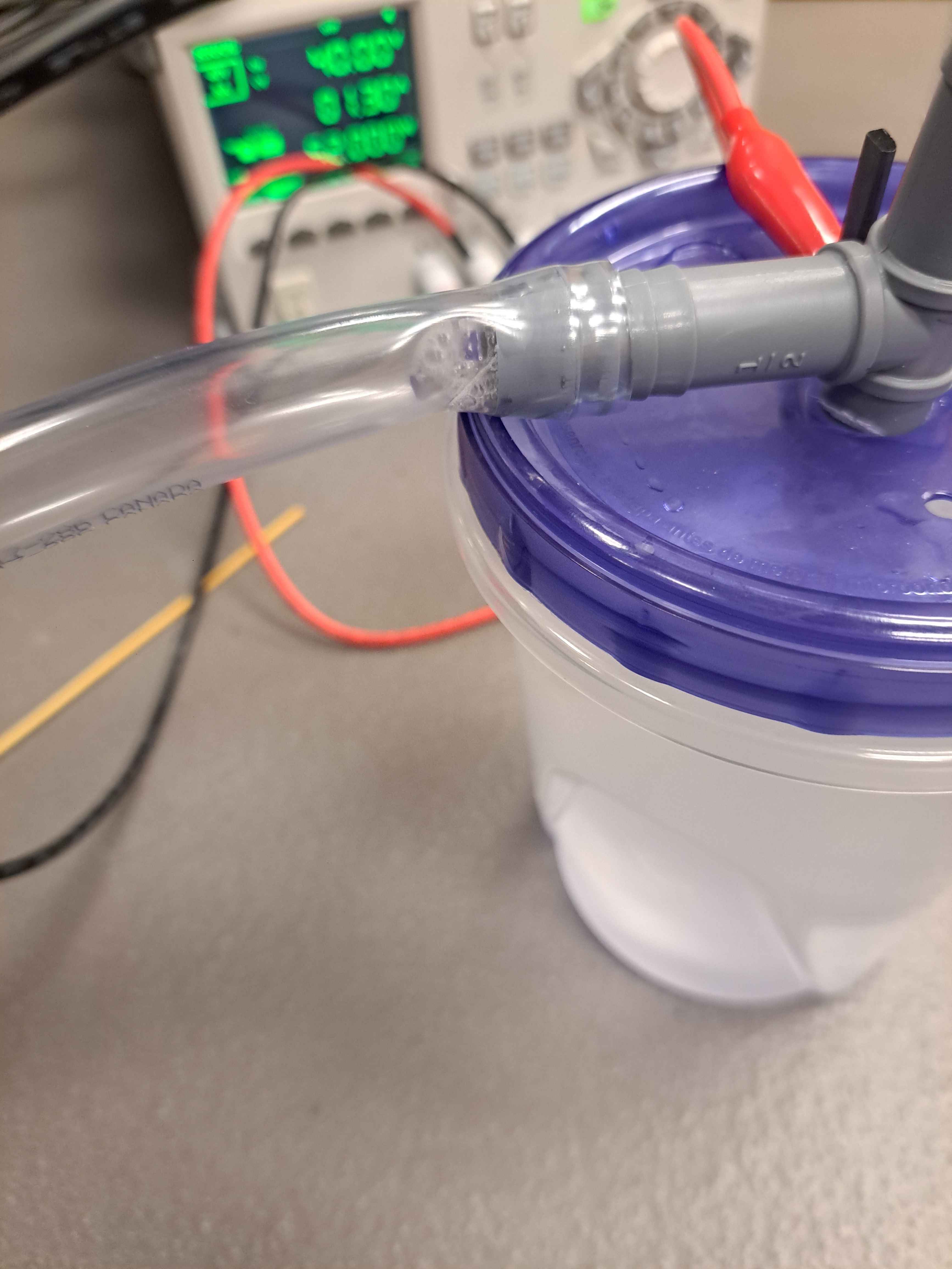
<p>The tee fittin had one side down in the container (hot glues to the lid, doesn't have to be airtight since the only leaks would be oxygen, the waste product). The top had a bit of graphite exposed for the alligator clip, this is the only one that needs to be as airtight as possible. I only had hot glue around so I used that, but will likely replace with sillicone or something else in later iterations. The third outlet was connected to the hose. There was a second graphite in the lid that was also glued to the lid (again, doesn't have to be airtight). There was also another vent hole drilled into the lid.</p>
<figure class="post__image"><img loading="lazy" src="https://jmarcano.ca/media/posts/15/20260726_200904.jpg" alt="" width="4624" height="3468" sizes="(min-width: 920px) 703px, (min-width: 700px) calc(82vw - 35px), calc(100vw - 81px)" srcset="https://jmarcano.ca/media/posts/15/responsive/20260726_200904-xs.jpg 300w ,https://jmarcano.ca/media/posts/15/responsive/20260726_200904-sm.jpg 480w ,https://jmarcano.ca/media/posts/15/responsive/20260726_200904-md.jpg 768w ,https://jmarcano.ca/media/posts/15/responsive/20260726_200904-lg.jpg 1024w">
<figcaption>The positive (oxygen) electrode on the right and the fitting with the hidden negative electrode on the left</figcaption>
</figure>
<p>The electrode for the hydrogen has to not show up bellow the fitting, otherwise there is a higher odds of hydrogen leaking outside the fitting from below. This was something I was able to see (not very visible in the picture). I also think my fitting doesn't go deep enough and doesn't allow enough surface area of the graphite.</p>
<figure class="post__image"><img loading="lazy" src="https://jmarcano.ca/media/posts/15/20260726_200918.jpg" alt="" width="3468" height="4624" sizes="(min-width: 920px) 703px, (min-width: 700px) calc(82vw - 35px), calc(100vw - 81px)" srcset="https://jmarcano.ca/media/posts/15/responsive/20260726_200918-xs.jpg 300w ,https://jmarcano.ca/media/posts/15/responsive/20260726_200918-sm.jpg 480w ,https://jmarcano.ca/media/posts/15/responsive/20260726_200918-md.jpg 768w ,https://jmarcano.ca/media/posts/15/responsive/20260726_200918-lg.jpg 1024w">
<figcaption>Top view of the setup, the small vent hole could be seen under the fitting.</figcaption>
</figure>
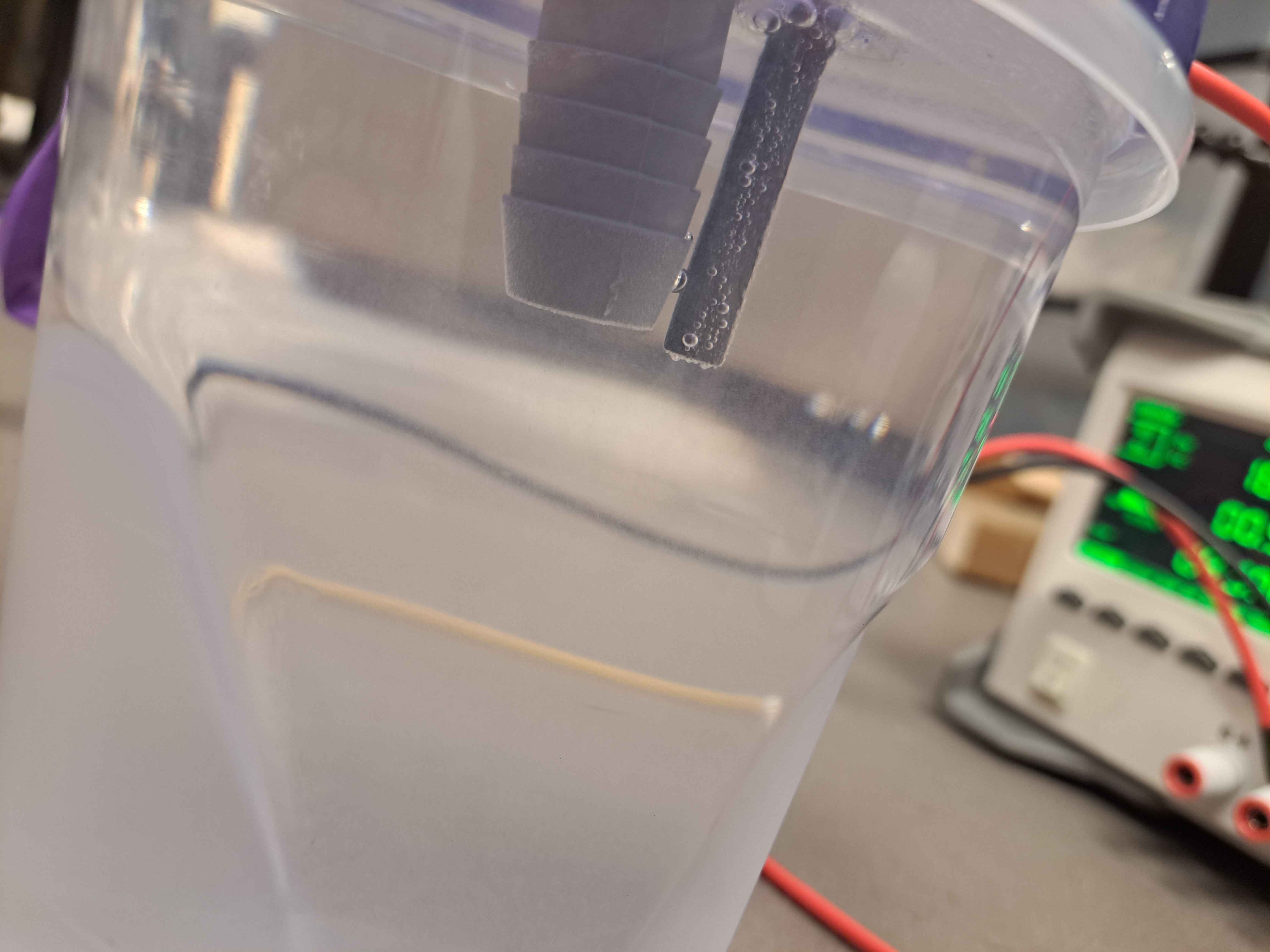
<p>Two interesting facts, that might be related. First, the current would consistently go down over time for a given voltage. If I put 30V 2A, after a few minutes it would drop to 30V 0.5A. I think this is can be because as the balloon fills, it puts pressure on the water, lowering its level and thus the efficiency of the positive electrode. I also think bubbles around the electrode effectively shield it from the water if production is too fast and can't clear the bubble fast enough. This is most evident after a bit at 30V, there were bubble that appeared at the tube outlet. These bubble left on their own, but maybe because the conversion rate dropped.</p>
<figure class="post__image"><img loading="lazy" src="https://jmarcano.ca/media/posts/15/20260726_201521-2.jpg" alt="" width="3468" height="4624" sizes="(min-width: 920px) 703px, (min-width: 700px) calc(82vw - 35px), calc(100vw - 81px)" srcset="https://jmarcano.ca/media/posts/15/responsive/20260726_201521-2-xs.jpg 300w ,https://jmarcano.ca/media/posts/15/responsive/20260726_201521-2-sm.jpg 480w ,https://jmarcano.ca/media/posts/15/responsive/20260726_201521-2-md.jpg 768w ,https://jmarcano.ca/media/posts/15/responsive/20260726_201521-2-lg.jpg 1024w">
<figcaption>Bubble appeared by the tube momentarily before leaving again</figcaption>
</figure>
<p>The balloon was able to inflate until taught, I didn't let it go much further since I don't expect the pressure to be this high in real use. I then let the balloon attached for a while to see if it would deflate on its own, a sign that there was a leak, and it did very slowly, so the setup could be improved.</p>
<p>I then tied the balloon off and weighed an empty balloon and the filled balloon to see how much lighter it got. The balloon, when "sphericized", was approximately 52mm diameter, and weighed 0.12g lighter. Supposedly it would be approximately 0.075g lighter if filled with pure hydrogen (heavier than that with anything else). I can chaulk up the difference to the balloons being different themselves. Still a good sign of it being pure hydrogen.</p>
<p>The production rate of gas follow Faraday's Law of Electrolysis:</p>
<p>$$\dot{n}=\frac{\eta I}{zF}$$</p>
<p>Where \(dot{n}\) is rate in moles per second, \(I\) is current in Amps, \(F\) is Faraday's constant (96 485As/mol), \(z\) is number of electrons per ion (2 for H2), and \(\eta\) is the efficiency (usually 0.9 to 0.99 if well done?). For the volume, we use the ideal gas law to get the approximate molar volume of \(\dot{V} \approx 22.4 L/mol\) at room temperature and ambient pressure.</p>
<p>This leads to a total volume production rate \(r\) of approximately, assuming a (conservative?) efficiency of 80%:</p>
<p>$$r(I)=\dot{V}\dot{n}=\frac{\eta I \dot{V}}{zF}=\frac{0.8 \cdot 22.4 \frac{L}{mol}}{2 \cdot 96.5 \frac{kAs}{mol}} I \approx 0.1 [\frac{ml}{As}] \cdot I [A]$$</p>
<p>This means for every amp that is pumped, I would get 0.1ml/s. This is very slow. The total volume of a 1m sphere (my generic metric) is 525L, which would imply:</p>
<p>$$t_{fill}=\frac{525 L}{0.1 \frac{ml}{As} \cdot I}=\frac{5.25}{I} Ms = \frac{1460}{I} hrs$$</p>
<p>Thats a lot of time! </p>
<h2 id="mcetoc_1juj5npjb689">July 27, 2026: Aluminium Reaction Design</h2>
<h3 id="mcetoc_1juj5npjb68a">9:00pm</h3>
<p>After further thinking, the pace of the electrolysis method will be too slow for in-field deployement. An alternative design, although <em><strong>WARNING</strong></em> more dangerous, is to mix lye and aluminium in water. The reaction that occurs is:</p>
<p>$$2Al_{(s)} + 2NaOH_{(aq)} + 6H_{2}O_{(l)} \longrightarrow 2Na[Al(OH)_{4}]_{(aq)} + 3H_{2(g)}$$</p>
<p>This reaction is very exothermic however so it needs to be designed with a lot of safety.</p>
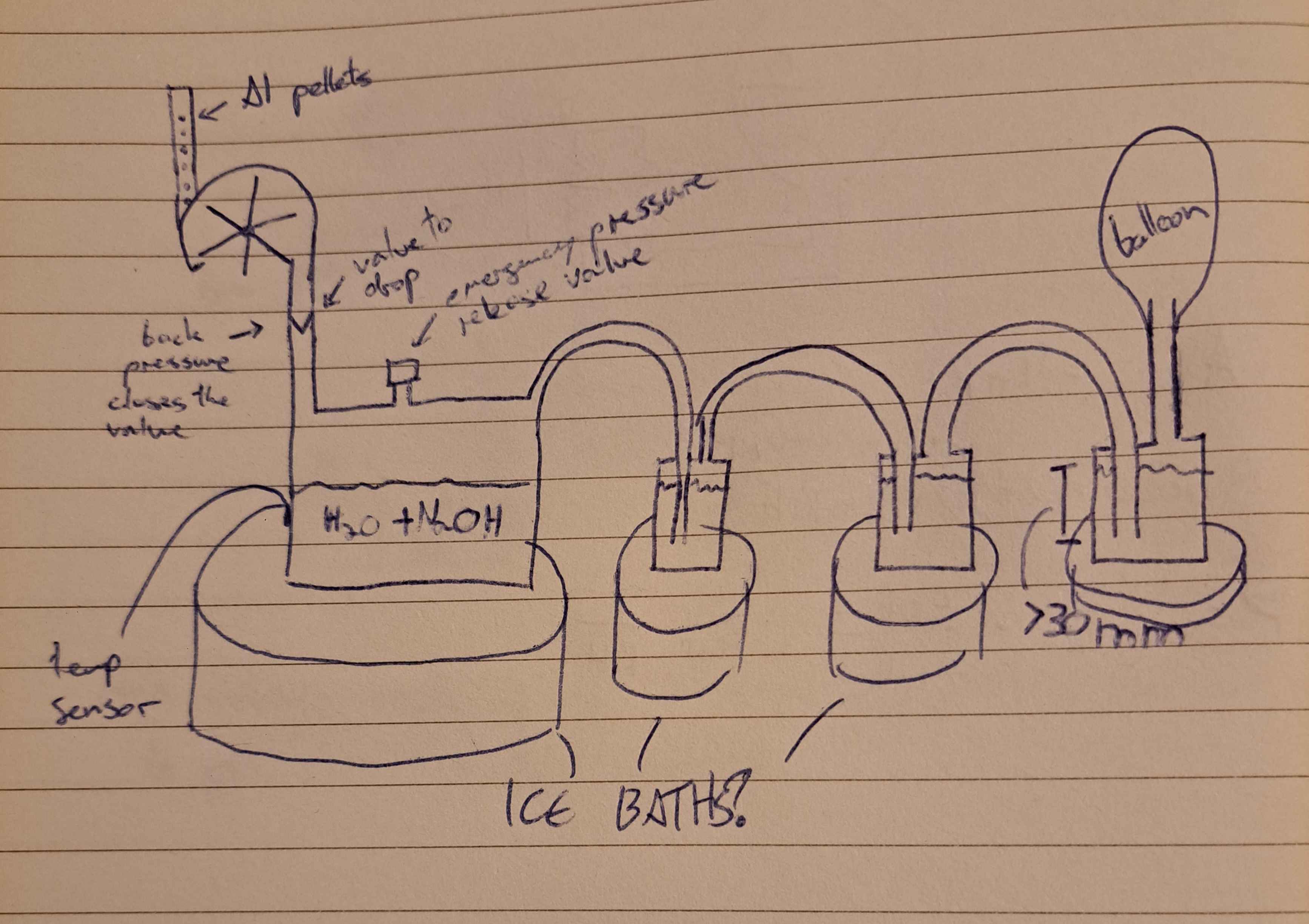
<p>The general idea is to have a mechanism that can safely drop a small amount of aluminium at a time, let the reaction occur and let the water cool back down before putting the next one. The main parts are the feeder and the cooling column. Since I don't have a cooling column and don't think it'll work perfectly, I think I will base my design in multiple water "arresters", where each one successively cools down the gas (letting the water vapour and any other gasses mix with the water. Only the hydrogen should keep going. The final one can connect directly to the balloon since the reaction should be capable of creating enough pressure.</p>
<p>Since the pressure from the balloon should only push the water down by 30mm, as long as the last arrestor is submerged with more than 30mm, it should be ok.</p>
<figure class="post__image"><img loading="lazy" src="https://jmarcano.ca/media/posts/15/20260727_213042.jpg" alt="" width="3468" height="2449" sizes="(min-width: 920px) 703px, (min-width: 700px) calc(82vw - 35px), calc(100vw - 81px)" srcset="https://jmarcano.ca/media/posts/15/responsive/20260727_213042-xs.jpg 300w ,https://jmarcano.ca/media/posts/15/responsive/20260727_213042-sm.jpg 480w ,https://jmarcano.ca/media/posts/15/responsive/20260727_213042-md.jpg 768w ,https://jmarcano.ca/media/posts/15/responsive/20260727_213042-lg.jpg 1024w">
<figcaption>First iteration of the Al design</figcaption>
</figure>
<p>Ideally the material used is something like Stainless Steel, but I feel it is important to be able to see inside the reaction as it occurs, so I'm not sure. The stell would make it easier to cool down the system in an ice bath or any active cooling solution. The later stages are likely not as critical.</p>
<p>One important thing to mention is that any metal should be grounded and possibly a mist will be sprayed as the balloon inflates since the balloon could have some static. It should also likely be placed on an ESD mat.</p>
<p>Since the vapour generated is caustic, every part of the reaction process should be made of material that can handle it.</p>
<p>The size of the pellets are also very important. Since they dictate the increments of gas that can be added at once (unless a second escape valve is added between the penultimate and ultimate arrester, which might be a good idea in general, also helps with emptying out the system of non-hydrogen before filling the balloon).</p>
<p>My current idea is to have the last (2?) containers be out of plastic (polypropylene) since they should neither deal with very cold nor very hot temperatures. Since plastic gets brittle and may start leaking if submerged at cold temperatures, it should also not be in an ice bath. The tubing by then can also be plastic if needed since it is cheaper.</p>
<p>The depth of the first arrester's tube indicates the resting pressure of the chamber, since that will determine when there is not enough pressure to go underneath the tube, at approximately 10mm per 100Pa.</p>
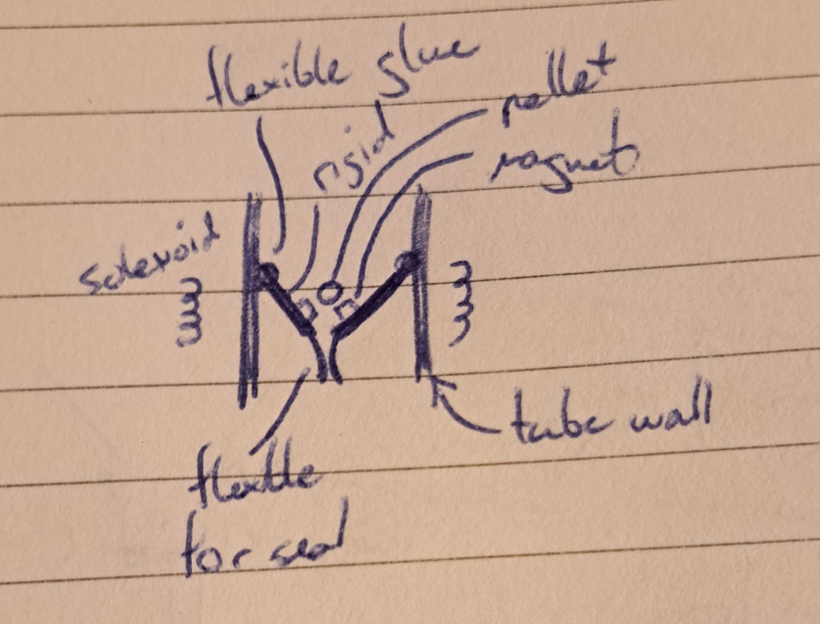
<p>The one way valve for the hopper section needs to be airtight when closed but let a small pellet in when opened. The design in mind is akin to what they use in water locks, which uses the pressure of the chamber itself to ensure the valve closes. This also makes it harder to accidentally open the valve when the reaction is pressurized a lot.  To operate the valve, maybe we can attach small magnets to silicone flaps. The flaps will prevent the backflow of pressure and the magnets, along with some solenoid on the outside, will allow it to open when we want the Al to fall through. Ideally some sort of silicone flap with a soft section at the end but a rigid in the center (like a spatula!). The hard part is the have the hinge be airtight as well. I am considering using a silicone glue that should stay relatively flexible for it. That tube can be square to make contruction easier. Since aluminium is not magnetic, it shouldn't get stuck on the magnets.</p>
<p>Neodynium might not like reacting with the water vapours. Even though it would be on the upper side and should be exposed to it, might be worth looking for alternates (cermic ferrite)?</p>
<p>Since the pellets should be small, the valve shouldn't have to open up very much.</p>
<figure class="post__image"><img loading="lazy" src="https://jmarcano.ca/media/posts/15/20260727_220620.jpg" alt="" width="2711" height="2064" sizes="(min-width: 920px) 703px, (min-width: 700px) calc(82vw - 35px), calc(100vw - 81px)" srcset="https://jmarcano.ca/media/posts/15/responsive/20260727_220620-xs.jpg 300w ,https://jmarcano.ca/media/posts/15/responsive/20260727_220620-sm.jpg 480w ,https://jmarcano.ca/media/posts/15/responsive/20260727_220620-md.jpg 768w ,https://jmarcano.ca/media/posts/15/responsive/20260727_220620-lg.jpg 1024w">
<figcaption>Valve setup</figcaption>
</figure>
<p>Speaking of the pellet size, we can find the approximate volume of gas produced per volume of Al. Every 2 mols of Al gives 3 mols of H2. Since Al has a density of 2.70g/cm3 and a molar mass of 26.98g/mol. Hydrogen gas on the other side is (under ideal gas law) 22.4L/mol. Thus:</p>
<p>$$\dot{V_{H_{2}}} = 22.4\frac{L}{mol_{H_{2}}} \cdot \frac{3}{2} \frac{mol_{H_{2}}}{mol_{Al}} \cdot \frac{1}{27}\frac{mol_{Al}}{g} = 1.24 \frac{L}{g_{Al}} \rightarrow 3.36\frac{L}{cm_{Al}^3}$$</p>
<p>Similarly for the lye (molar mass of 40g/mol):</p>
<p>$$\dot{V_{H_{2}}} = 22.4\frac{L}{mol_{H_{2}}} \cdot \frac{3}{2} \frac{mol_{H_{2}}}{mol_{NaOH}} \cdot \frac{1}{40}\frac{mol_{NaOH}}{g} = 0.84 \frac{L}{g_{NaOH}}$$</p>
<p>For the same 1m diameter sphere (525L) that means approximately 625g of NaOH and 420g of Al. This is much more reasonable.</p>
<p>Howver this does mean that the pellets of Al needed are relatively small. If we want 1% control for the sphere, that means approximately 4.2g per pellet. However 5.25L at a time might be alot, especially if it needs to be stopped in an emergency.</p>
<p>500g of Al as a 1/8 inch rod has a length of:</p>
<p>$$L = \frac{V}{\pi r^2} = \frac{m}{\pi \rho r^2} = \frac{500g}{\pi 2.70\frac{g}{cm^3} (0.3175cm)^2} = 5.85m$$</p>
<p>For a 1/4 inch rod:</p>
<p>$$L = \frac{500g}{\pi 2.70\frac{g}{cm^3} (0.635cm)^2} = 1.46m$$</p>
<p>Each 5g pellet would then be 1.46cm tall, very reasonable.</p>
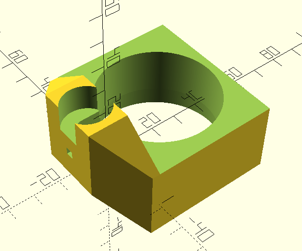
<p>To make the feeder, I will use pvc hose, since I already have some as the magazine, which will then get pushed via a servo (mostly because I already have one and they are cheap enough). This then falls into a 2 inch (or 1 1/2 inch) PVC pipe that will contain the valve. Then at the bottom will be the container. The valve will exhaust air into the enironment, but that is likely safer than letting any amount of the vapours interact with the rod in the magazine.</p>
<figure class="post__image"><img loading="lazy" src="https://jmarcano.ca/media/posts/15/Screenshot-2026-07-28-003612.png" alt="" width="617" height="513" sizes="(min-width: 920px) 703px, (min-width: 700px) calc(82vw - 35px), calc(100vw - 81px)" srcset="https://jmarcano.ca/media/posts/15/responsive/Screenshot-2026-07-28-003612-xs.png 300w ,https://jmarcano.ca/media/posts/15/responsive/Screenshot-2026-07-28-003612-sm.png 480w ,https://jmarcano.ca/media/posts/15/responsive/Screenshot-2026-07-28-003612-md.png 768w ,https://jmarcano.ca/media/posts/15/responsive/Screenshot-2026-07-28-003612-lg.png 1024w">
<figcaption>The magazine hose goes on the left, the pipe from underneath on the right and the push rod in the slot in the far left.</figcaption>
</figure>
<p>All that section before the valve can be 3D printed. It will make it easier to iterate and replace. I need to finish the mount for the servo motor behind the push rod slot. I also need to design the flaps for the valv. It will likely be a 1 flap design instead of 2, since it'll make there be less magnets inside the setup (that can interact with each other).</p>
            ]]>
        </content>
    </entry>
    <entry>
        <title>Radlands Review</title>
        <author>
            <name>JAMR</name>
        </author>
        <link href="https://jmarcano.ca/radlands-review.html"/>
        <id>https://jmarcano.ca/radlands-review.html</id>
            <category term="board games"/>

        <updated>2026-07-24T21:32:05-04:00</updated>
            <summary type="html">
                <![CDATA[
                    I am a big fan of the game. This page is not done, it is mostly a placeholder
                ]]>
            </summary>
        <content type="html">
            <![CDATA[
                <p>I am a big fan of the game.</p>
<p>This page is not done, it is mostly a placeholder</p>
            ]]>
        </content>
    </entry>
    <entry>
        <title>Weather Balloon Exploration</title>
        <author>
            <name>JAMR</name>
        </author>
        <link href="https://jmarcano.ca/weather-balloon-exploration.html"/>
        <id>https://jmarcano.ca/weather-balloon-exploration.html</id>
            <category term="weather balloon"/>
            <category term="in progress"/>
            <category term="ham radio"/>
            <category term="electronics"/>

        <updated>2026-07-24T21:07:43-04:00</updated>
            <summary type="html">
                <![CDATA[
                    I want to attempt to make a weather balloon module that can send images and telemetry and be recoverable easily to send up. Ideally it&hellip;
                ]]>
            </summary>
        <content type="html">
            <![CDATA[
                <p>I want to attempt to make a weather balloon module that can send images and telemetry and be recoverable easily to send up.</p>
<p>Ideally it is:</p>
<ul>
<li>Robust: Needs to survive landing</li>
<li>Has a parachute to help it land</li>
<li>Can take pictures and send them over ham radio lines
<ul>
<li>Can also saved them locally</li>
</ul>
</li>
<li>Can transmit its location, height and other telemetry constantly
<ul>
<li>Needs to work while in the air, and (at least partially) while on the ground.</li>
</ul>
</li>
</ul>
<h2>July 25, 2026</h2>
<p>Officially starting the project. I have fleshed out a bit more the needed requirements for it to work.</p>
<p>Requirements:</p>
<ul>
<li>BOM Costs:
<ul>
<li>Total BOM should be less than 200$ (ammortized for a qty of 10)</li>
<li>Consumables (balloon, air, etc.) should be &lt;75$, ideally ~50$</li>
</ul>
</li>
<li>In-Flight Transmission:
<ul>
<li>Continuous images (every few minutes)
<ul>
<li>Should also saved a tighter timelapse locally for recovery</li>
</ul>
</li>
<li>Continuous telemetry</li>
<li>Continuous GPS to be able to point antenna and follow it</li>
<li>Backup APRS/WSPR in case main comms go down</li>
<li>Nice to have would be a continuous video transmission</li>
</ul>
</li>
<li>Post-Flight Transmission:
<ul>
<li>Only GPS needs to be transmitted, but needs to work even on the ground</li>
</ul>
</li>
<li>Payload:
<ul>
<li>Battery needs to last at least 12hrs (including flight time)</li>
<li>Payload needs to be in working condition and fit for another flight
<ul>
<li>This also includes the temperatures in the air</li>
<li>Includes the landing, might require a (late) parachute to help it</li>
</ul>
</li>
<li>Likely keep the weight below 4 pounds (maximum weight in the States)</li>
</ul>
</li>
</ul>
<p>Becuase of these requirements, particularly the BOM costs, helium is an unlikely candidate for the baloon filling. Ideally, we are able to set up a system with electrolysis to generate a supply of hydrogen and fill trhe balloon (remotely) with it.</p>
<p>Thus the project splits into 3 main subsystems:</p>
<ol>
<li>Flight subsystem</li>
<li>Filling and release subsystem</li>
<li>Ground station subsystem</li>
</ol>
<h3>1. Flight Subsystem</h3>
<p>This is the classic part of the project. It is the part that actually gets to fly. It will likely be composed for 4 parts:</p>
<h4>A. Balloon</h4>
<p>This is likely the easiest part. I plan to simply source one from a store. It simply needs to be a latex balloon that is biodegradable. The law in Canada is that the balloon must be less than 115 cubic feet at launch.</p>
<p>For reference, maybe something like <a href="https://a.co/d/01dTJLqd" target="_blank" rel="noopener noreferrer">this</a> (just a quick search, will likely need to spend more time to properly source one).</p>
<h4>B. Payload</h4>
<p>This will house the elctronics and the battery. It needs to withstand the temperatures at altitude safely, which might require a heater, and it limited to about 4 pound of weight. From what I see, most people use a styrofoam outter casing to protect it from fluctuating temperatures. Might be worth looking into. Maybe can also use the transmitter as a source of heat for the battery.</p>
<h4>C. Parachute/Recovery</h4>
<p>This one is still not known if we need it, but likely will imply an active parachute system that deploys when the device is near the ground, simply to slow it down. The reason I do not want it to start from too high is to prevent it from being blown by the wind much more.</p>
<p>It is likely that we can use a hobby rocketry-style parachute, which would be easier to source.</p>
<h4>D. Antenna(s)</h4>
<p>The antennas depend a lot on the bands we use. Any HF band could easy have a long wire antenna underneath/above the payload without too many issues. This antenna needs to have a decently wide FOV since we won't be able to predict when the payload will end up relative to the ground station.</p>
<h3>2. Filling and Release Subsystem</h3>
<p>This part is likely the most dangerous, but also the simplest. The idea is that using electrolysis, it should be possible to get a very cheap supply of very pure hydrogen. It will consist of 3 parts.</p>
<h4>A. Electrolysis</h4>
<p>This section is simply distilled water with some current carriers (salts) along with 2 electrodes. One of the electrodes will be the section that generates the hydrogen. This means there is a separation between the two and it will funnel into a hydrogen supply outlet. The ON/OFF and power control from this will be remotely controlled (using a wired connection). This will allow for monitoring and safety by not needing to have someone nearby.</p>
<h4>B. Outlet</h4>
<p>This section is in charge of making sure the hydrogen goes inside the balloon only in one way. It is also responsible for sealing the balloon once it is full, so some automated way should be figured out (a one way valve perhaps).</p>
<p>The hardest part of this is that it needs to make sure that the hydrogen has enough pressure to go into the balloon. Maybe a water based system, where the hydrogen goes through water is the simplest way. However it prevents the use of a one way valve from being part of the balloon system, so an alternate way of sealing the balloon would be necessary.</p>
<h4>C. Release mechanism</h4>
<p>This section is in charge of holding down the balloon until it is filled enough and having a way to sense when it acheives neutral bouyancy (+ free lift requirements). Once that is reached, it is able to separate the outlet from the balloon (in tandem with the outlet sealing the balloon), and releasing its grip from it so it can go in the air. It needs to be tall enough to have the electronics not drag on the ground as it is released.</p>
<h3>3. Ground Station Subsystem</h3>
<p>This subsystem should have a fixed mode and a mobile mode. The fixed mode is for when the balloon is in flight. Ideally it can have a directional antenna that can track the balloon to always have a lock on it and get the best performance for downlinks. The mobile is simply in charge of the recovery process and so should be able to jump on a car and follow a signal. It includes a laptop/computer that can log all the information it gathers, and not go haywire if it momentarily looses track. Ideally you can access APRS/WSPR from it as a failsafe and redundancy.</p>
<p> </p>
            ]]>
        </content>
    </entry>
    <entry>
        <title>Custom Bookcase</title>
        <author>
            <name>JAMR</name>
        </author>
        <link href="https://jmarcano.ca/custom-bookcase.html"/>
        <id>https://jmarcano.ca/custom-bookcase.html</id>
        <media:content url="https://jmarcano.ca/media/posts/11/20260716_220946.jpg" medium="image" />
            <category term="random"/>
            <category term="completed"/>

        <updated>2026-07-24T20:14:58-04:00</updated>
            <summary type="html">
                <![CDATA[
                        <img src="https://jmarcano.ca/media/posts/11/20260716_220946.jpg" alt="" />
                    I am not a good woodworker, but it pays to learn. We wanted a bookcase that fit our needs well and couldn't find one, so&hellip;
                ]]>
            </summary>
        <content type="html">
            <![CDATA[
                    <p><img src="https://jmarcano.ca/media/posts/11/20260716_220946.jpg" class="type:primaryImage" alt="" /></p>
                
  <p>
    I am not a good woodworker, but it pays to learn. We wanted a bookcase that fit our needs well and couldn't find one, so we decided to make our own.
  </p>

    <h2 id="july-25-2026">
      July 25, 2026
    </h2>

  <p>
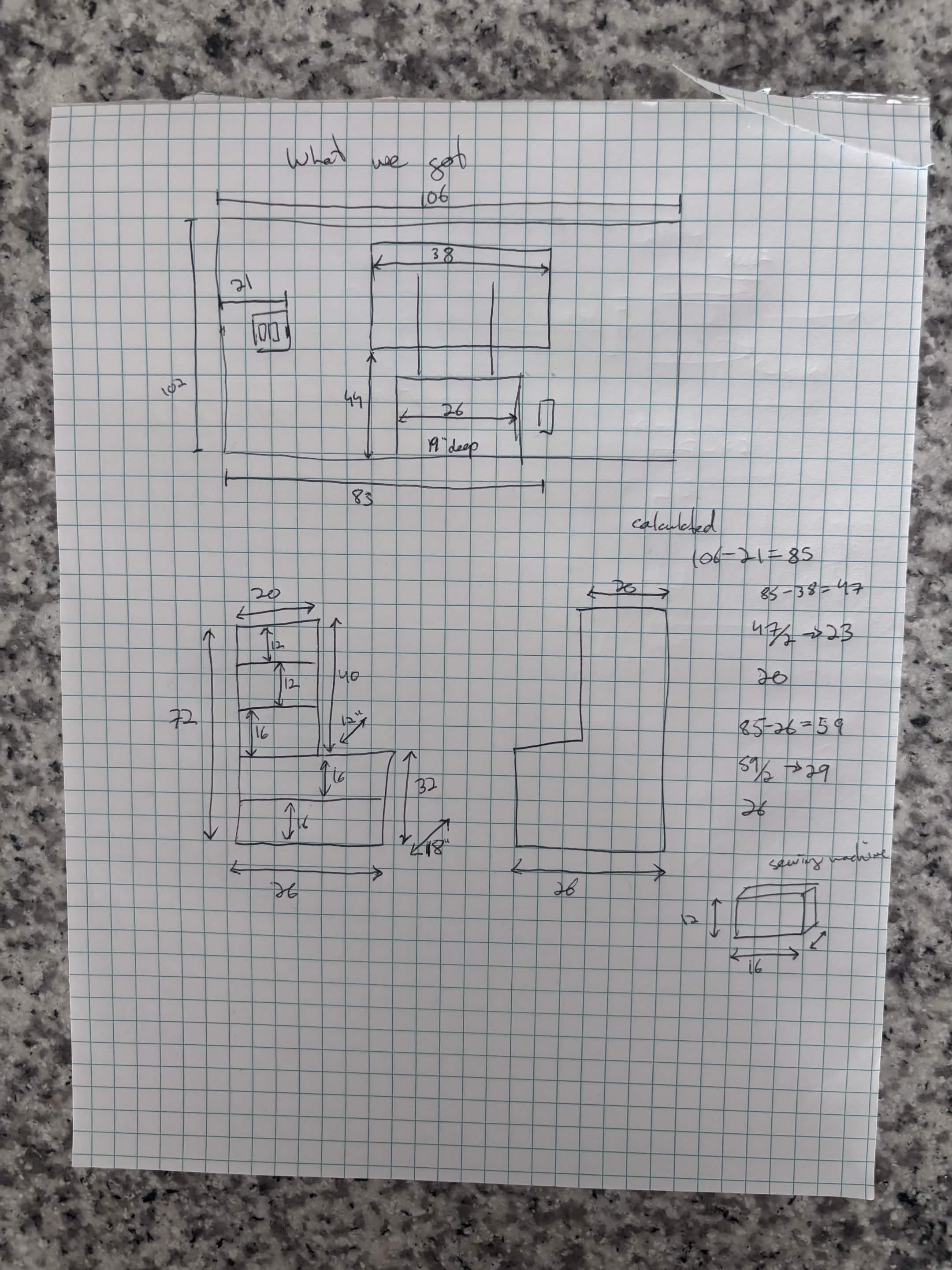
    The general premise was that we had a rolling TV stand and wanted to make a bookcase that fit within our space constrained apartment while still allowing for the TV to move around. It also needed to fit a lot of books and my hobby equipment. The hobby equipment put a minimum dimension on the shelves: at least 16 inches deep and 12 inches tall. However, such deep bookshelves were not very efficient for books since, unless double stacked (which, why would you given the possibility not to), there would be a lot of lost space in front of the books.
  </p>

    <h3 id="the-design">
      The design
    </h3>

  <p>
    We looked at possible bookcases at Ikea, but none fit the description well. We did however, use the trip for inspiration. Upon our empty handed return, we started planning the ideal bookshelf. We were constrained on the sides by the end of the wall&nbsp; on one side and the switch on the other. We also needed to account for the TV stand. Since the TV stand was wider at the TV than on the wheels, We decided on a two-tiered design, where the bottom would hold the hobby stuff by being deeper and taller, while the top is smaller and would hold the books. This would also allow us to make two of them to hug either side of the TV stand
  </p>

    <figure class="post__image post__image--center">
      <img loading="lazy" src="https://jmarcano.ca/media/posts/11/IMG_6570.jpg" height="2880" width="2160" alt=""  sizes="(min-width: 920px) 703px, (min-width: 700px) calc(82vw - 35px), calc(100vw - 81px)" srcset="https://jmarcano.ca/media/posts/11/responsive/IMG_6570-xs.jpg 300w ,https://jmarcano.ca/media/posts/11/responsive/IMG_6570-sm.jpg 480w ,https://jmarcano.ca/media/posts/11/responsive/IMG_6570-md.jpg 768w ,https://jmarcano.ca/media/posts/11/responsive/IMG_6570-lg.jpg 1024w">
      <figcaption>The dimensions and constrains along with our initial design</figcaption>
    </figure>

    <h3 id="the-sourcing">
      The sourcing
    </h3>

  <p>
    We first did a stakeout of the hardware store to see what kind of wood we could use. Since we went right before closing, we mostly simply got to browse the different woods, and their sizes. Due to price and strength, we decided to go for some plywood over solid wood. The cuts they had went up to 4x8 feet. So we did some quick, back of the napkin math to figure out how many pieces we would need. Using simple area calculation, it showed that each 4x8 would be able to make 1 bookcase.
  </p>

  <p>
    We also looked around at the staining and varnishing (neither of us had done any woodworking so it was a mix of googling and asking around). Since the cleanest, nicest looking while not breaking the bank wood we found was 1/2 inch red oak plywood, staining was allegedly easy. We opted to using brackets as our main fasteners since they are easy to design and strong.
  </p>

  <p>
    We then spent the evening trying to fit a bookshelf into 1 of those plywood pieces. This took some puzzling around, but by shrinking one of our dimensions slightly (by reducing the height from 40 inches to 38), we were able to do it.
  </p>

  <p>
    [insert notebook picture here]&nbsp;
  </p>

  <p>
    With the spare pieces of wood, we were also able to get footers for the front and the back. We also designed some additional support for the middle shelf since that one would need to hold the top shelf in the middle of&nbsp; the shelf and we didn't want it sagging.
  </p>

    <h3 id="the-making">
      The making
    </h3>

  <p>
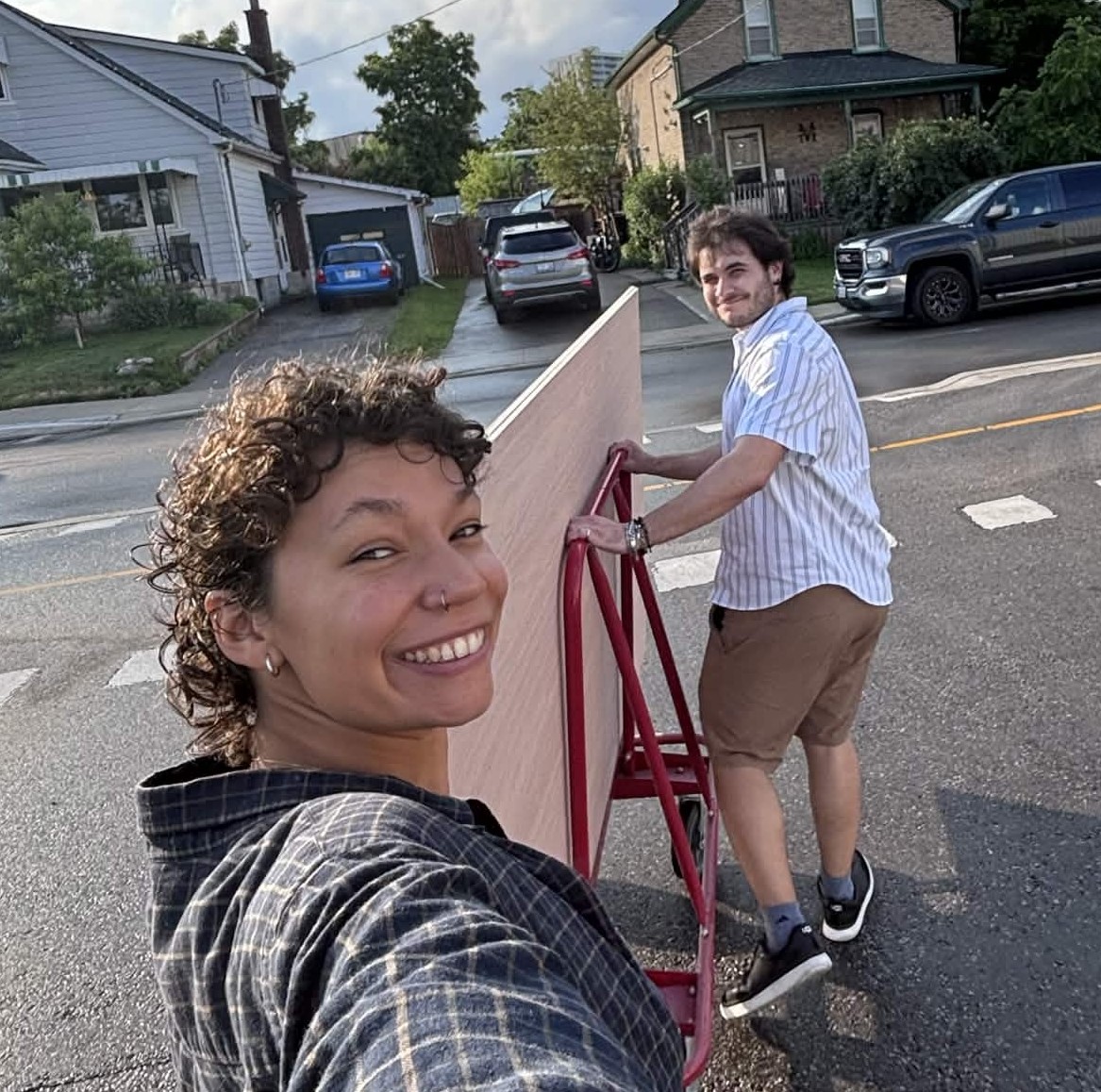
    We got the wood and brought it to my workplace's woodshop. We borrowed a wood cart from the workplace since it was conveniently a block away from the hardware store. The first evening was spent just cutting the wood down to size. It required 3 people to do it since the table saw was not very big and the pieces of wood were.
  </p>

    <figure class="post__image post__image--center">
      <img loading="lazy" src="https://jmarcano.ca/media/posts/11/IMG_6577.jpg" height="1158" width="1167" alt=""  sizes="(min-width: 920px) 703px, (min-width: 700px) calc(82vw - 35px), calc(100vw - 81px)" srcset="https://jmarcano.ca/media/posts/11/responsive/IMG_6577-xs.jpg 300w ,https://jmarcano.ca/media/posts/11/responsive/IMG_6577-sm.jpg 480w ,https://jmarcano.ca/media/posts/11/responsive/IMG_6577-md.jpg 768w ,https://jmarcano.ca/media/posts/11/responsive/IMG_6577-lg.jpg 1024w">
      <figcaption>Casually taking the wood out of the store</figcaption>
    </figure>

  <p>
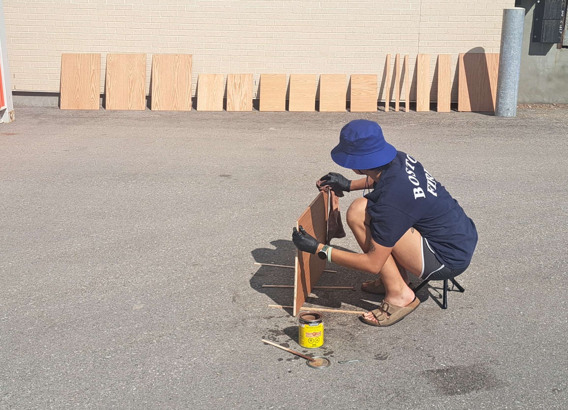
    The second day (Saturday) was the most brutal. While in the middle of a heatwave, we had to stain the wood outdoors. I didn't write down the temperature, but easily in the mid-30s (high 80s). We did light sanding before applying the stain, mostly following this <a href="https://youtu.be/xvuCT7AQWFs?si=MLSKEzwHgwzHNC8c" rel="nofollow noopener">video</a>. We used Minwax Cherry as the stain since we didn't want it to be very dark. We then let the wood rest overnight in a well ventilated area.
  </p>

    <figure class="post__image post__image--center">
      <img loading="lazy" src="https://jmarcano.ca/media/posts/11/20260627_1700261.jpg" height="1666" width="2308" alt=""  sizes="(min-width: 920px) 703px, (min-width: 700px) calc(82vw - 35px), calc(100vw - 81px)" srcset="https://jmarcano.ca/media/posts/11/responsive/20260627_1700261-xs.jpg 300w ,https://jmarcano.ca/media/posts/11/responsive/20260627_1700261-sm.jpg 480w ,https://jmarcano.ca/media/posts/11/responsive/20260627_1700261-md.jpg 768w ,https://jmarcano.ca/media/posts/11/responsive/20260627_1700261-lg.jpg 1024w">
      <figcaption>Staining the wood. It was brutally hot that day. You can see some of the pieces in the back</figcaption>
    </figure>

  <p>
    The next day, we went back and, thankfully indoors, we applied the finish. We went with&nbsp;Varathane Diamond Satin wood finish. We chose satin over gloss since we wanted a more natural looking look. We applied 3 coats, with approximately 1 hour in between the first 2 coats and 2 hours between the second and third coat. Since there were so many pieces of wood, it took us all day to do...
  </p>

    <h3 id="the-assembly">
      The assembly
    </h3>

  <p>
    The bookcases were assembled (by design) in two parts. This would make it easy to move them if the need ever arose.
  </p>

  <p>

    The bottom half was assembled, every shelf has two 1 1/2 inch L brackets on either side. The bottom-most shelf used 1 inch brackets only had 1 on either side and 1 holding the footers (which also had 1 on either end to attach it to the side panels). The support beam was screwed into the top shelf (of the bottom) using 4 screws from the bottom so that they wouldn't be visible.
  </p>

  <p>
    The top similarly used 2 brackets on either side on each shelf, but the brackets were 1 inch brackets.
  </p>

  <p>
    The bottom half exhibited a significant amount of racking (side to side wiggle) which was very concerning. The top also had some but less, likely owning to the fact that it had 3 shelves instead of 2. This caused me to be very weary of attaching the two halves together using the original plan of the Ikea-like screws and fasteners.
  </p>

  <p>

    After days of thinking and dooming, I ended up going with a wall mounted approach (initially we had thought of only using 1 anti-tipping anchor). This implied using 3 anchors into the drywall to prevent any motion side to side. Using one anchor at the middle shelf and 2 anchors on the top shelf, the entire body would be rigid and not allow for much torque around the middle. To attach the middle, I wanted something I could easy separate and reattach easily, but ended up going for more L brackets just to be safe. I figured if needed, we could use wood inserts if we need to disassembled and reassemble it anyways. I made sure those brackets landed on the support beam underneath.
  </p>

  <div  class="gallery-wrapper">
    <div class="gallery" data-columns="3">
      <figure class="gallery__item">
      <a href="https://jmarcano.ca/media/posts/11/gallery/20260716_220818.jpg" data-size="6936x9248">
        <img loading="lazy" src="https://jmarcano.ca/media/posts/11/gallery/20260716_220818-thumbnail.jpg" height="1024" width="768" alt="" >
      </a>
      
    </figure><figure class="gallery__item">
      <a href="https://jmarcano.ca/media/posts/11/gallery/20260716_211137.jpg" data-size="9248x6936">
        <img loading="lazy" src="https://jmarcano.ca/media/posts/11/gallery/20260716_211137-thumbnail.jpg" height="576" width="768" alt="" >
      </a>
      
    </figure>
    </div>
  </div>

    <h2 id="the-final-thoughts">
      The final thoughts
    </h2>

  <p>
    While not a perfect job, I think it turned out great for a first attempt. We went in without very much planning and a lot of winging it as we went, but adapted pretty well. The stain looks good but the lack of edge binding meant that the raw plywood edge was visible. I personally do not mind it but I can see how it might not be the most pleasant view.
  </p>

  <p>
    The biggest thing I learnt was that L brackets aren't perfect and damn, staining and finishing take a very long time if you are doing a lot of wood!
  </p>

  <p>
    [insert image of both bookshelves]
  </p>
            ]]>
        </content>
    </entry>
    <entry>
        <title>Bookcase Mats</title>
        <author>
            <name>JAMR</name>
        </author>
        <link href="https://jmarcano.ca/bookcase-mats.html"/>
        <id>https://jmarcano.ca/bookcase-mats.html</id>
        <media:content url="https://jmarcano.ca/media/posts/9/20260707_000849.jpg" medium="image" />
            <category term="short"/>
            <category term="sewing"/>

        <updated>2026-07-24T20:14:55-04:00</updated>
            <summary type="html">
                <![CDATA[
                        <img src="https://jmarcano.ca/media/posts/9/20260707_000849.jpg" alt="" />
                    I made a bookcase and wanted to protect the shelves from constant inserting and taking out things like the sewing machine and oscilloscope. So I&hellip;
                ]]>
            </summary>
        <content type="html">
            <![CDATA[
                    <p><img src="https://jmarcano.ca/media/posts/9/20260707_000849.jpg" class="type:primaryImage" alt="" /></p>
                
  <p>
    I made a bookcase and wanted to protect the shelves from constant inserting and taking out things like the sewing machine and oscilloscope. So I decided to make mats. I also wanted tassels.
  </p>

    <h2 id="july-25-2026">
      July 25, 2026
    </h2>

  <p>
    The requirements are quite simple, the main use is to prevent scratching on the wooden surface. The other requirements are that it should not slip very much and should have tassels. The tassels not only serve for decoration, but they also help hide some of the plywood edge without the need for edge banding.
  </p>

  <p>
    I started by going to a fabric store (<a href="https://lensmill.com/" target="_blank" rel="nofollow noopener">Len's Mill</a>) and purchasing some fabric.
  </p>

    <h3 id="the-fabric">
      The fabric
    </h3>

  <p>
    The fabric for the top could be almost any, so it is mostly whatever I find pretty. The only thing was to make sure it was strong and wouldn't rip. I got an embroidered fabric (I don't know the blend to be honest). The colour is chosen as a very light beige to not be easy to get dirty but not dark since the bookshelf is not a very dark colour and didn't want to darken the style.
  </p>

  <p>
    [insert photo here of the fabric]
  </p>

  <p>
    The fabric for the bottom only needs to be non-slip and of the same colour theme as the top. I went for a beige felt, thinking that it is thick and I wouldn't need to worry about fraying, which would simplify the finishing of the mat, since anything thick, if finished, would give a big bulky edge around my mat.
  </p>

  <p>
    [insert photo here of the felt fabric]
  </p>

  <p>

    The shelves are 26x18 inches, and I needed to line 4 of them. I do not remember the total amount of fabric I got, but likely got a lot more than needed.
  </p>

  <p>
    I also got some tassels that matched the colour very well and looked nice but nothing too crazy. I also do not remember how much of this I got.
  </p>

  <p>
    [insert photo of tassel]
  </p>

    <h3 id="the-cutting">
      The cutting
    </h3>

  <p>
    I knew that the top was going to be folded over and sewn into the bottom and finished at the same time. However, I hadn't yet figured out in what manner. I still, however, cut the pieces before figuring it out...
  </p>

  <p>
    I started by cutting the the top fabric to have half an inch extra on either side. So 27x19 inches. This would allow for them to fold over. I then cut the felt to the exact size of the shelf (I then trimmed it down after I figured out to finish it, but no spoilers).
  </p>

    <h3 id="the-finishing">
      The finishing
    </h3>

  <p>
    With some scrap fabric, I tried some different finished, thinking about the thickness and the overall look. The main things I looked out for was:
  </p>

  <ul>
    <li>No bulk on the edges</li><li>Felt should not be visible out of the edges</li><li>The tassels should be easy to sew in</li><li>Not too crazy to do since I am not very good</li>
  </ul>

  <p>
    [insert picture of different finished here]
  </p>

  <p>
    Since the thread colour I had was very invisible after sewing, I had plenty of freedom on doing hidden stitches. I still ended up going for a single zigzag stich, making sure to grab the felt underneath. This was both as a serge and a stitch in one, although the fraying would mostly be protected by being encased in the felt and the good side.
  </p>

    <h3 id="issues">
      Issues
    </h3>

  <p>
    There were a couple of issues I faced on the first one. I will see if I can prevent them on the other ones.
  </p>

  <p>
    The first was the cutting. I was kind of lazy and hastily cut it without much regard for straightness. This came to bite me later on...
  </p>

  <p>
    I also didn't spend much time thinking about how to do the corners. This led to issues during the sewing phase that I still need to figure out for the other 3.
  </p>

  <p>
    It was also hard to make sure the stitch was straight and always grabbed the same amount of felt. I got better at this near the end of the first one, but the non-straight edges had me struggling to figure out if I should be following the edge of the felt or the top fabric.
  </p>

  <p>

    The felt likely made the mat more slippery, not less. It does at least not scratch the surface at all, but makes it such that if the sewing machine is taken out, it has a chance of pulling out the rest of the things on the shelf.
  </p>

  <div  class="gallery-wrapper">
    <div class="gallery" data-columns="3">
      <figure class="gallery__item">
      <a href="https://jmarcano.ca/media/posts/9/gallery/20260707_000849-2.jpg" data-size="6936x5202">
        <img loading="lazy" src="https://jmarcano.ca/media/posts/9/gallery/20260707_000849-2-thumbnail.jpg" height="576" width="768" alt="" >
      </a>
      <figcaption>The final design</figcaption>
    </figure><figure class="gallery__item">
      <a href="https://jmarcano.ca/media/posts/9/gallery/20260707_000900-2.jpg" data-size="6936x9248">
        <img loading="lazy" src="https://jmarcano.ca/media/posts/9/gallery/20260707_000900-2-thumbnail.jpg" height="1024" width="768" alt="" >
      </a>
      <figcaption>The felt underside and finishing</figcaption>
    </figure><figure class="gallery__item">
      <a href="https://jmarcano.ca/media/posts/9/gallery/20260707_001831-2.jpg" data-size="6936x9248">
        <img loading="lazy" src="https://jmarcano.ca/media/posts/9/gallery/20260707_001831-2-thumbnail.jpg" height="1024" width="768" alt="" >
      </a>
      <figcaption>The mat properly populated with stuff</figcaption>
    </figure>
    </div>
  </div>
            ]]>
        </content>
    </entry>
    <entry>
        <title>High sensitivity 2m band </title>
        <author>
            <name>JAMR</name>
        </author>
        <link href="https://jmarcano.ca/high-sensitivity-2m-band.html"/>
        <id>https://jmarcano.ca/high-sensitivity-2m-band.html</id>
            <category term="in progress"/>
            <category term="ham radio"/>
            <category term="electronics"/>

        <updated>2026-07-24T20:14:53-04:00</updated>
            <summary type="html">
                <![CDATA[
                    The purpose of this is to learn how to design receivers capable of handling very weak signals. The goal is to be able to listen&hellip;
                ]]>
            </summary>
        <content type="html">
            <![CDATA[
                
  <p>
    The purpose of this is to learn how to design receivers capable of handling very weak signals. The goal is to be able to listen to the&nbsp;AO-73 (FUNcube-1).
  </p>
            ]]>
        </content>
    </entry>
    <entry>
        <title>Altoideck - A Cyberdeck Exploration</title>
        <author>
            <name>JAMR</name>
        </author>
        <link href="https://jmarcano.ca/altoideck.html"/>
        <id>https://jmarcano.ca/altoideck.html</id>
        <media:content url="https://jmarcano.ca/media/posts/3/20260611_024532.jpg" medium="image" />
            <category term="on hold"/>
            <category term="in progress"/>
            <category term="electronics"/>

        <updated>2026-07-24T19:47:32-04:00</updated>
            <summary type="html">
                <![CDATA[
                        <img src="https://jmarcano.ca/media/posts/3/20260611_024532.jpg" alt="" />
                    This project is trying to make a cyberdeck that fits entirely inside an Altoid can. This is a retrospective of the project so far. I&hellip;
                ]]>
            </summary>
        <content type="html">
            <![CDATA[
                    <p><img src="https://jmarcano.ca/media/posts/3/20260611_024532.jpg" class="type:primaryImage" alt="" /></p>
                
  <p>
    This project is trying to make a cyberdeck that fits entirely inside an Altoid can.
  </p>

    <h2 id="july-24-2026">
      July 24, 2026
    </h2>

  <p>
    This is a retrospective of the project so far. I will go into more details later but the gist of it is this:
  </p>

  <ul>
    <li>Has an OLED screen</li><li>Is battery powered off of a 1S LiPo</li><li>Has a USB (for charging and as a device only, no hosting) and an SD Card</li><li>Detects when the lid is open using magnets and a reed switch</li><li>Is powered by an ESP32</li>
  </ul>

  <p>
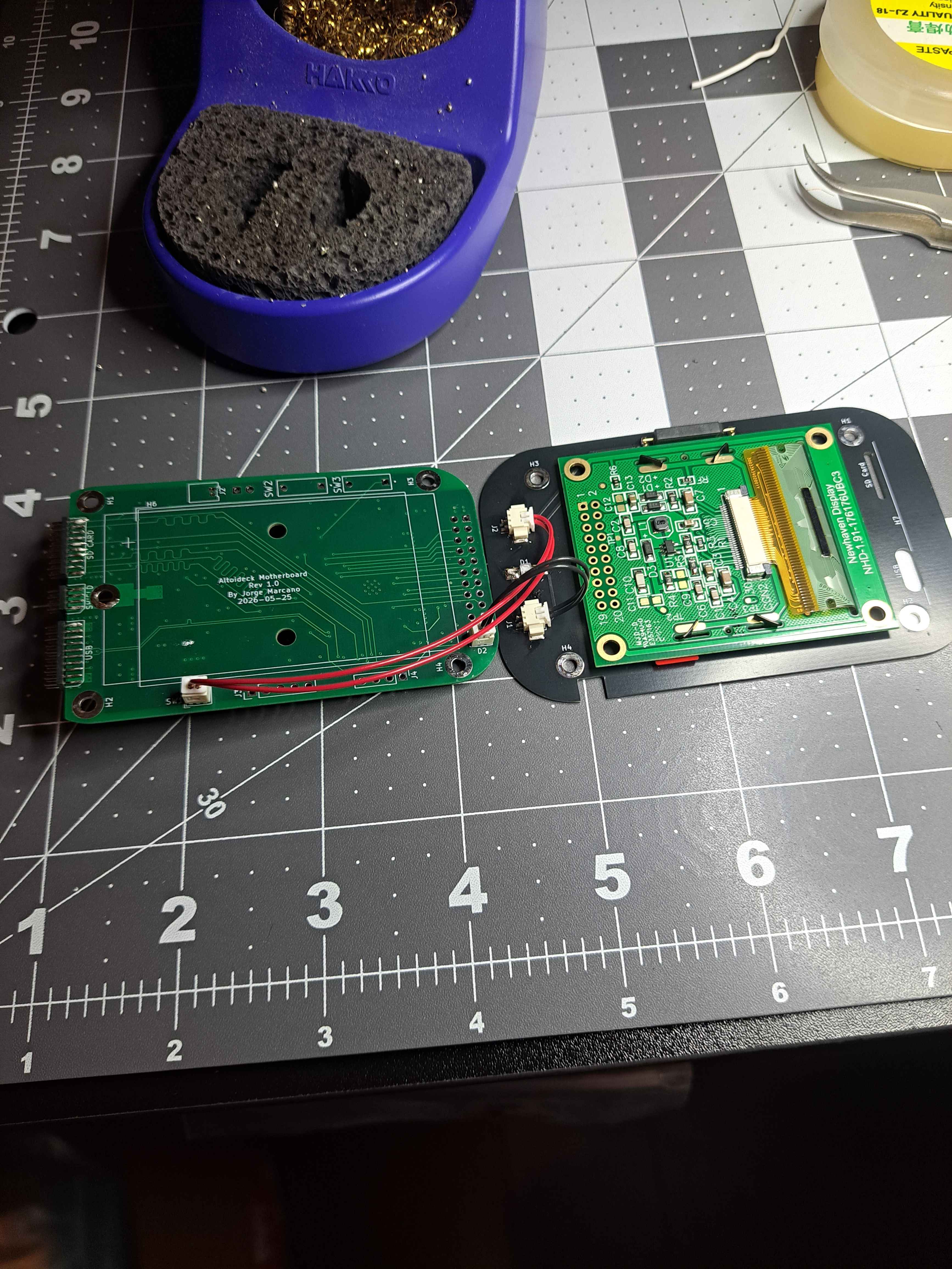
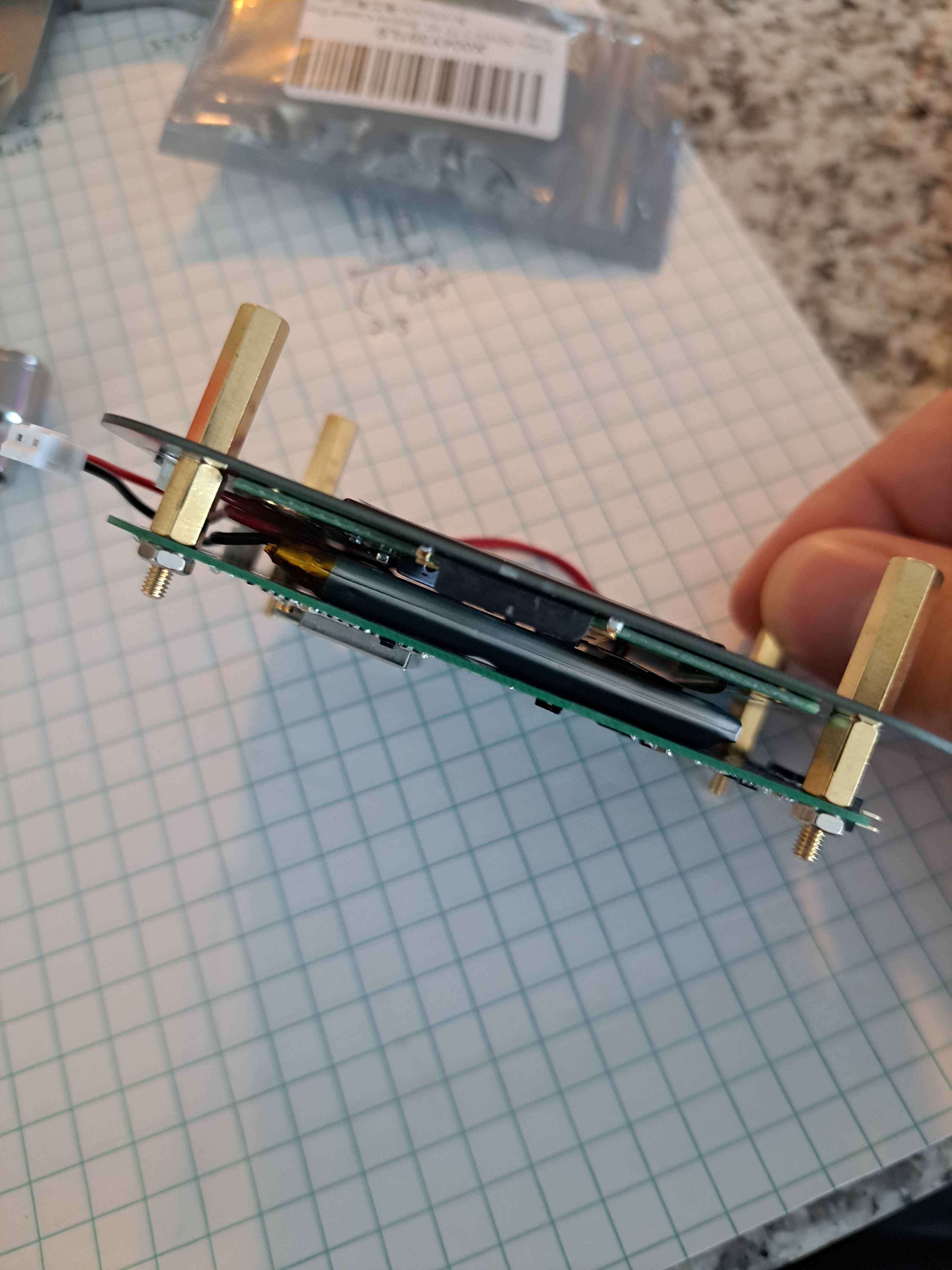
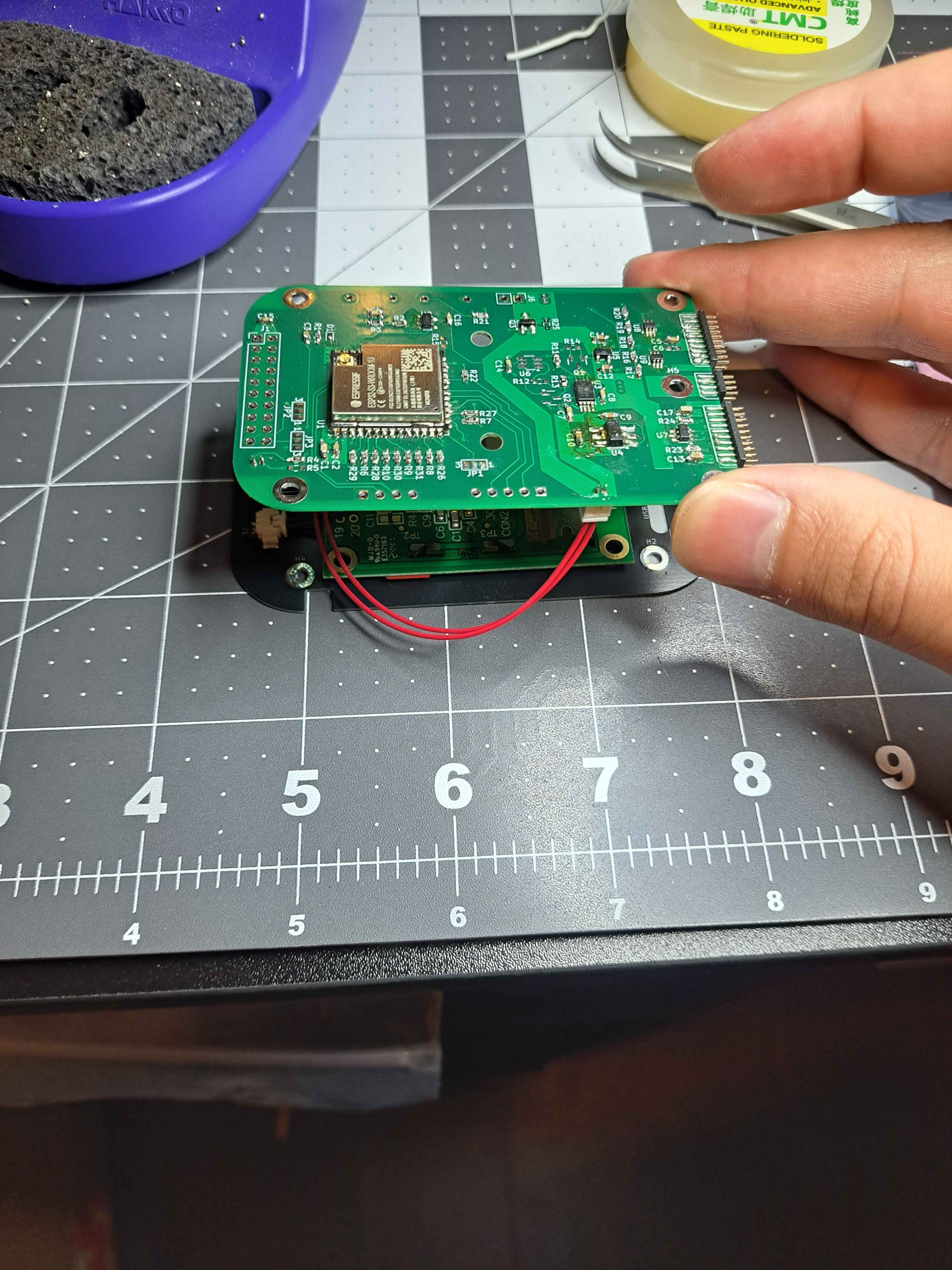
    The hardest part of the design was trying to ensure there was enough vertical spacing to fit everything. The boards were as thin as possible (while still being cheap enough), the battery as was size according to the remaining space.
  </p>

  <p>
    The screen module was bought as a module to save on BOM costs and complexity, but also to allow for it to be easily adapted to any other display technology.
  </p>

  <p>
    The keyboard is custom and still a work in progress. The boards are done but the assembly isn't.
  </p>

  <p>
    The current part I am stuck at is the supports to hold everything. This will be 3D printed but requires making a negative of everything to fill in as many of the gaps as possible to improve the stability of the boards and the assembly.
  </p>

  <p>
    I will be making a more in depth description of all the boards and decisions at a later date.
  </p>

  <div  class="gallery-wrapper">
    <div class="gallery" data-columns="3">
      <figure class="gallery__item">
      <a href="https://jmarcano.ca/media/posts/3/gallery/20260610_232224.jpg" data-size="3468x4624">
        <img loading="lazy" src="https://jmarcano.ca/media/posts/3/gallery/20260610_232224-thumbnail.jpg" height="1024" width="768" alt="PCB with some components" >
      </a>
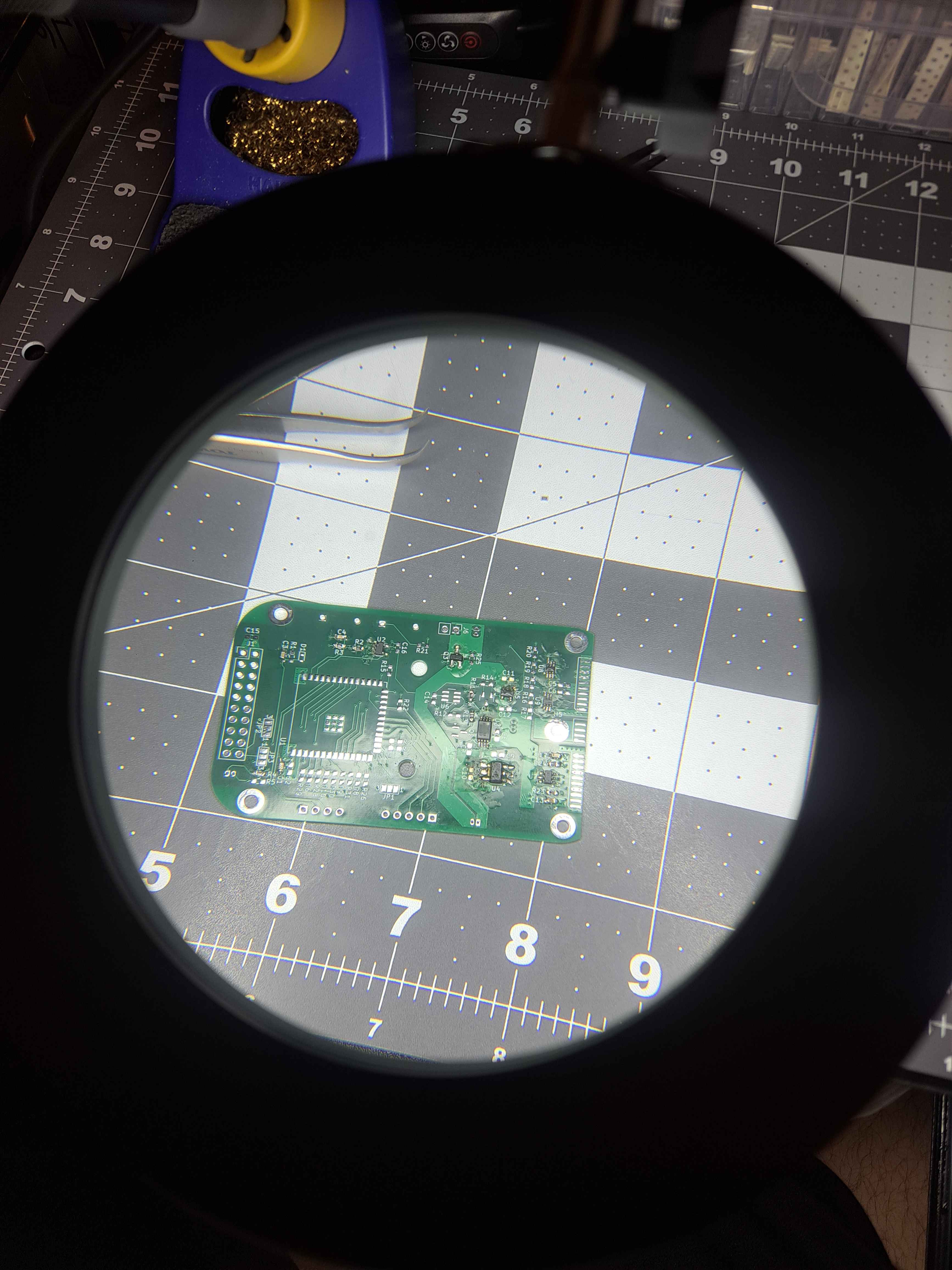
      <figcaption>The Motherboard midway through soldering</figcaption>
    </figure><figure class="gallery__item">
      <a href="https://jmarcano.ca/media/posts/3/gallery/20260619_195512.jpg" data-size="3468x4624">
        <img loading="lazy" src="https://jmarcano.ca/media/posts/3/gallery/20260619_195512-thumbnail.jpg" height="1024" width="768" alt="" >
      </a>
      <figcaption>The top half assembled with temporary spacers to verify spacing</figcaption>
    </figure><figure class="gallery__item">
      <a href="https://jmarcano.ca/media/posts/3/gallery/20260611_024539.jpg" data-size="3468x4624">
        <img loading="lazy" src="https://jmarcano.ca/media/posts/3/gallery/20260611_024539-thumbnail.jpg" height="1024" width="768" alt="" >
      </a>
      <figcaption>The top half upside down</figcaption>
    </figure>
    </div>
  </div>
            ]]>
        </content>
    </entry>
</feed>